Common Faults and Troubleshooting of Current Transformers Faults
Abstract
Current transformers (CTs) are essential components of power metering systems. Faults during their operation can significantly increase energy measurement errors by affecting the transformation ratio. To reduce these errors, it is crucial to identify and manage CT faults effectively. This article outlines the basic principles of current transformers, analyzes common operational faults, and provides practical troubleshooting methods to address them.
Introduction to Current Transformers
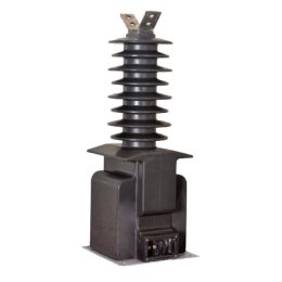
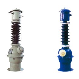
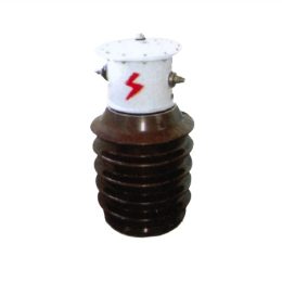
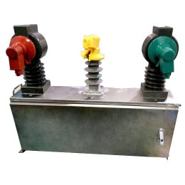
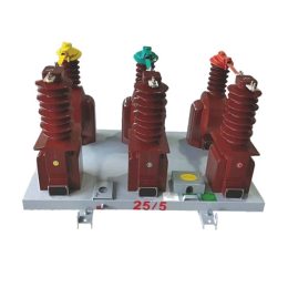
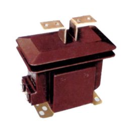
Current transformers are critical devices in power systems that convert large primary currents into smaller, standardized secondary currents for measurement and protection. They work similarly to transformers, with the primary difference being that CTs transform current instead of voltage. This makes CTs indispensable for ensuring the operational safety and efficiency of power systems.
Key Characteristics of Current Transformers:
- Secondary Circuit Load: The CT’s secondary circuit typically connects to instruments or relay protection devices, operating at low impedance, resembling a short-circuit condition. The primary current is determined by the load and remains independent of the secondary circuit, ensuring measurement accuracy.
- Secondary Circuit Restrictions: The secondary winding of a CT must not operate open-circuited. In such cases, the lack of opposing magnetic flux leads to core saturation, high induced voltage, and increased losses, posing safety risks and potentially damaging the CT.
Common Causes of CT Faults
CT faults often result from operational or structural issues. Key causes include:
- Defective Terminal Construction: Poor-quality terminal materials or design flaws can cause loose connections, leading to circuit interruptions during operation.
- Maintenance Errors: Failing to properly connect critical components, such as relay protection devices, increases the likelihood of faults.
- Improper Connector Alignment: Misaligned or excessively long insulation on connectors may prevent proper contact, resulting in circuit failures.
- Loose Secondary Terminals: Weak or loose connections in secondary terminals can cause overheating, oxidation, or damage under high current loads.
Fault Diagnosis and Troubleshooting
Identifying Open Circuit Faults
To diagnose open circuit faults, use the following methods:
- Monitor Instrument Readings: Unusual drops to zero or erratic fluctuations in current or power meter readings often indicate open circuit issues.
- Listen for Unusual Sounds: Abnormally loud or uneven noises from the CT core may suggest magnetic flux issues caused by open circuits.
- Inspect for Sparks or Discharges: High voltage generated during open circuit faults can cause sparking or insulation damage at terminals or connection points.
Resolving Secondary Open Circuit Faults
- Prioritize safety by using insulated tools, gloves, and mats while diagnosing faults. Refer to accurate wiring diagrams to identify affected circuits.
- Report the fault to system operators and disable protection systems to prevent false triggers.
- Reduce the primary current load to minimize risks during repairs. If the CT is severely damaged, transfer the load to other circuits before inspection.
- Short-circuit the secondary terminals near the fault location using reliable connectors and inspect for sparks. If sparks occur, the fault lies downstream; otherwise, it is upstream. Investigate systematically to pinpoint the issue.
- Focus on inspecting terminals and components in the fault area, especially those disturbed during previous maintenance.
Conclusion
Current transformers are vital for energy measurement and power system protection, but faults in their operation can compromise reliability and accuracy. Identifying and addressing common fault causes, such as defective terminals or secondary circuit issues, is critical for maintaining CT performance. Regular maintenance, thorough inspections, and effective troubleshooting ensure the safe and efficient operation of power systems. This analysis offers valuable insights for managing CT faults, helping to enhance power system reliability and measurement precision.
- Causes and Solutions for False Fault Alarms in Zero-Sequence Current Transformers
- Error Analysis and Maintenance of Current Transformers in Power Systems
- Instrument Transformer Fault Handling: A Technical Guide
- Fault Handling Considerations for Current and Voltage Transformers
- Common Fault Handling for Current and Voltage Transformers
- Zero-Sequence Current Transformers vs. Standard Current Transformer
