Analysis of the Impact of Incorrect CT S1 and S2 Connections and Reversed Input Lines
The Role of S1 and S2 in Current Transformers
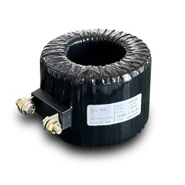
In a current transformer, the S1 and S2 terminals are designed to handle the input and output of primary current to the secondary circuit. S1 represents the primary side input, while S2 is the output. This directional connection ensures the proper phase relationship between the primary and secondary currents, which is essential for accurate measurement, protection, and energy metering. CT S1 and S2 Connections, current transformer wiring.
Consequences of Reversing S1 and S2 Connections
Measurement Inaccuracies
Reversing S1 and S2 disrupts the electromagnetic induction principle on which CTs operate. This error causes the phase of the secondary current to oppose the primary current, leading to significant measurement inaccuracies. The displayed current may differ from the actual current, potentially showing negative values. Such inaccuracies undermine effective system monitoring and decision-making.
Protection System Errors
Protection devices rely on CT signals to determine fault conditions and initiate corrective actions. When S1 and S2 are reversed, the phase error can send incorrect signals to the protection system. This may result in the following:
- Misoperation: The protection system might trip unnecessarily during normal conditions.
- Failure to Operate: The system might fail to trip during an actual fault, endangering system stability and equipment safety.
Metering Discrepancies
For energy metering systems, the accuracy of CT wiring directly impacts billing and energy tracking. Reversing S1 and S2 can distort energy consumption data, resulting in billing inaccuracies and potential disputes over energy charges.
Effects of Reversed Input Lines
Anomalies in Secondary Circuits
Reversing the primary or secondary input lines disrupts the flow of current and voltage signals, causing errors in the secondary circuit. These anomalies can:
- Generate incorrect readings in measurement instruments.
- Lead to false triggering or failure of protection devices.
System Instability
Proper coordination between power system components is essential for stability. Reversed input lines disturb this balance, potentially causing oscillations or, in extreme cases, system failure. Such instability threatens the reliability of the entire power network.
Challenges in Maintenance
Fault detection and repair become significantly more difficult when input lines are reversed. The resulting anomalies in the secondary circuit complicate troubleshooting, increasing both the cost and time required for maintenance. This can further disrupt normal operations and delay system restoration.
Recommendations for Preventing Wiring Errors
Strict Adherence to Wiring Standards
During installation and maintenance, it is critical to follow industry-standard wiring protocols. Each CT terminal must be carefully labeled and connected according to the design to avoid errors.
Thorough Testing and Inspection
Before energizing the system, conduct comprehensive testing to verify the accuracy of CT connections. Tools like phase testers and polarity meters can help identify and correct wiring mistakes early.
Enhanced Training and Awareness
Investing in training programs for electrical personnel is essential. Workers should understand the consequences of wiring errors and be equipped with the knowledge to prevent and identify them. Practical workshops and hands-on training can significantly reduce the occurrence of mistakes.
Use of Advanced Monitoring Systems
Integrating advanced diagnostic and monitoring systems can aid in real-time detection of wiring errors. Automated alerts can help operators address issues promptly, minimizing the impact on system performance.
Conclusion
Incorrect wiring of CT terminals, including reversed S1 and S2 connections and input line reversals, can have severe implications for measurement accuracy, system protection, energy metering, and overall stability. These errors not only compromise the functionality of the power system but also increase maintenance complexity and costs. By adhering to strict wiring standards, conducting thorough inspections, and enhancing workforce training, such errors can be effectively prevented. Ensuring accurate CT connections is crucial for maintaining the safety, efficiency, and reliability of modern power systems.
- Zero-Sequence Current Transformer Protection Principle and Applications
- Analysis of the Impact of Incorrect CT S1 and S2 Connections and Reversed Input Lines
- Error Analysis and Maintenance of Current Transformers in Power Systems
- Analysis and Troubleshooting of Common Issues with Current Transformers
- Common Fault Handling for Current and Voltage Transformers
- Troubleshooting Techniques for Burnt Voltage Transformers


