Overview
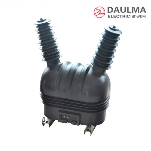
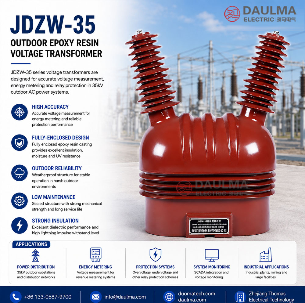
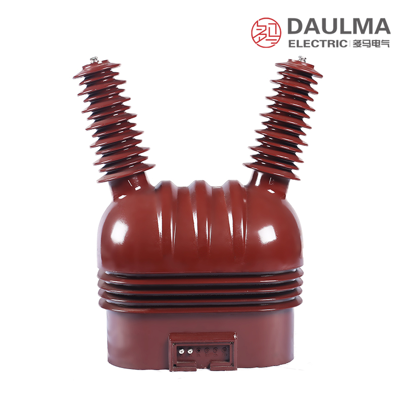
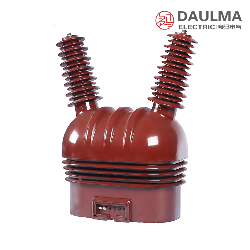
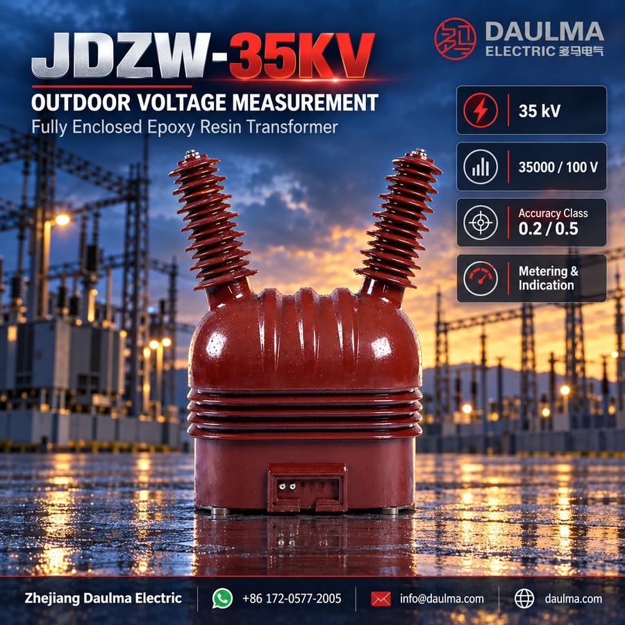
The JDZW-35KV outdoor fully enclosed epoxy resin voltage transformer is a precision electromagnetic instrument engineered for accurate voltage measurement, energy metering, and relay protection in 35kV AC power systems. Operating on Faraday’s law of electromagnetic induction, it delivers galvanically isolated secondary voltage signals proportional to the primary system voltage while maintaining precise phase relationships.
Built for rugged outdoor service, this transformer features a pillar-type mounting design with fully sealed epoxy resin insulation that ensures long-term resistance to moisture, UV radiation, pollution, and mechanical stressâmaking it ideal for substations and distribution networks exposed to harsh environmental conditions.
Key Ratings Snapshot
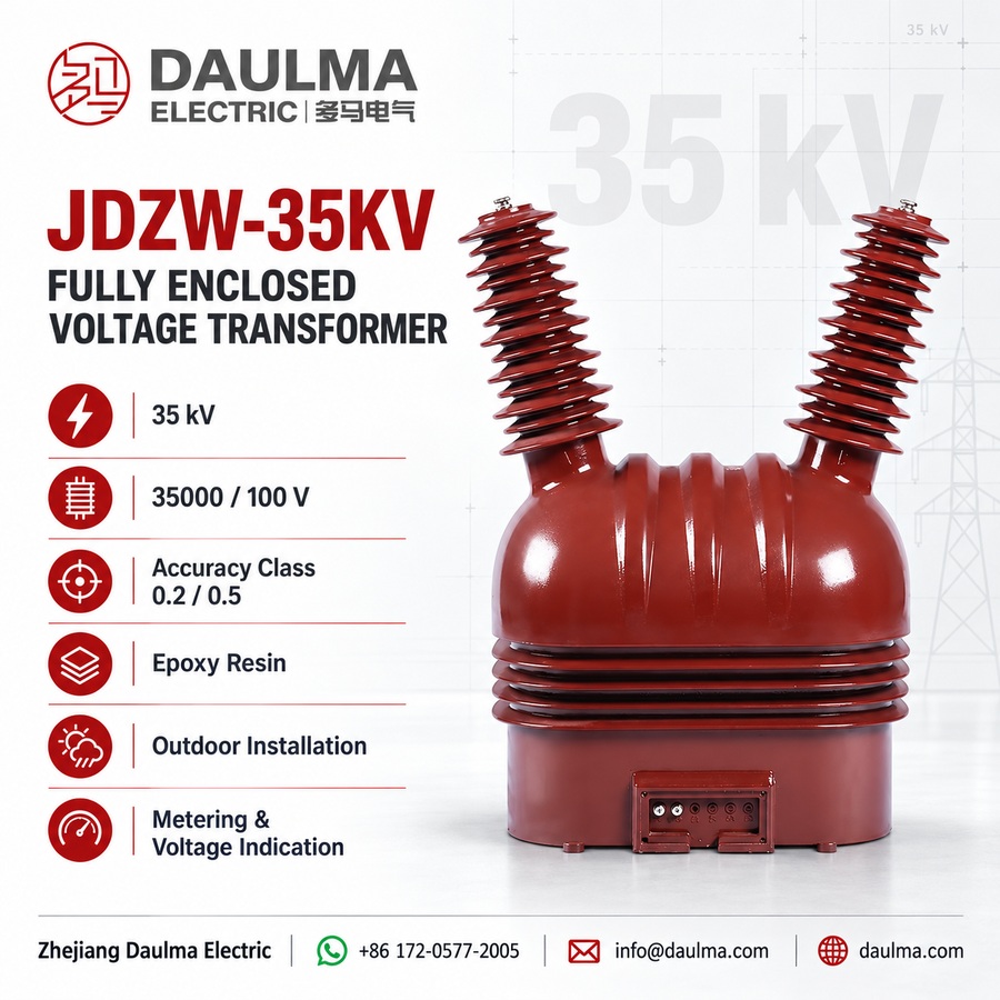
| Item | Specification |
|---|---|
| System voltage class | 35 kV (outdoor) |
| Rated frequency | 50 Hz (60 Hz on request) |
| Rated secondary voltage | 100 V or 100/â3 V |
| Accuracy classes | 0.2, 0.5 (metering); 6P (protection) |
| Rated burden | Per core as specified (VA) |
| Burden power factor | cosÏ = 0.8 (lagging) |
| Insulation level | 40.5/95/200 kV (Um/LIPL/ACSD) |
| Applicable standards | IEC 61869-3, GB/T 20840.3 |
| Model variant | JDZW-35 |
| Construction type | Epoxy resin cast, fully enclosed, post-type |
Model Designation

- J: Voltage transformer (VT / PT)
- D: Single-phase design
- Z: Support (pillar / post) type
- W: Outdoor installation
- 35: Voltage class (kV)
Construction
The JDZW-35KV features a robust pillar-type structure designed for secure outdoor mounting. Its core is built from cold-rolled grain-oriented silicon steel laminations, heat-treated for optimal magnetic performance. The entire assembly is encapsulated using advanced vacuum casting technology with UV-resistant, anti-tracking epoxy resin, eliminating internal voids and ensuring uniform dielectric strength.
This fully enclosed design provides exceptional resistance to moisture ingress, surface tracking, pollution, and agingâcritical for reliable operation in coastal, industrial, or high-humidity environments. The terminal box is metal-enclosed with a sealed, padlockable cover and multiple cable entry points, ensuring secure and tamper-resistant secondary connections.
Technical Parameters
Service Conditions
- Installation environment: Outdoor
- Altitude: <= 1000 m above sea level
- Ambient temperature: -5 deg C to +40 deg C
- Relative humidity: Daily average <= 95%, monthly average <= 90% (at +20 deg C)
- Environmental conditions: Free from corrosive gases, explosive media; pollution severity level II per IEC 60815
Technical Data
| Model | Voltage Ratio (V) |
Accuracy Class Combination |
Rated Output (VA) |
Maximum Output (VA) |
Insulation Level (kV) |
|---|---|---|---|---|---|
| JDZW-35 | 35000/100 | 0.2 | 75 | 1000 | 40.5/95/200 |
| JDZW-35 | 35000/100 | 0.5 | 100 | 1000 | 40.5/95/200 |
Frequently Asked Questions
Q1: What are the outdoor installation altitude limits for this 35kV voltage transformer?
The maximum installation altitude is 1000 meters above sea level. For higher elevations, specific derating factors apply. Contact factory engineering for high-altitude project requirements.
Q2: Which accuracy class should I select for metering versus protection applications?
Select the 0.2 class for precision metering and 0.5 class for general measurement. Custom accuracy combinations require factory consultation prior to ordering. This ensures correct burden matching for your specific application.
Q3: What is the insulation level for the 35000/100V epoxy resin transformer?
The rated insulation level is 40.5/95/200 kV. This fully enclosed epoxy resin design ensures reliable performance in pollution severity level II environments. Verify specific clearance distances with your switchgear layout.
Q4: Can we customize the voltage ratio and rated output burdens?
Yes, custom voltage ratios and burden ratings are available subject to factory engineering confirmation. Standard models offer 75VA or 100VA rated output. Please specify your exact requirements when requesting a quote.
Q5: Are factory test reports provided with the standard 35kV transformer shipment?
Yes, all ratings are verified per the nameplate and factory test report. Custom configurations require prior engineering consultation. Request specific documentation requirements when placing your procurement order.
Q6: What applications are suitable for this outdoor 35kV voltage transformer?
This epoxy resin voltage transformer is ideal for outdoor 35kV power distribution and substations. It provides reliable voltage step-down for measurement and protection relays. Contact our sales team for application-specific technical support.
Q7: How does ambient temperature affect the operational limits of this transformer?
The standard operating ambient temperature range is -5°C to +40°C. Daily relative humidity must not exceed 95%. Consult the factory if your site experiences extreme temperature fluctuations beyond these parameters.
Q8: Where is this epoxy resin voltage transformer manufactured and supplied?
Our JDZW-35KV transformers are manufactured to international IEC standards for global supply. They are designed for outdoor 35kV substations worldwide. Contact our regional distributor for localized shipping and support details.
Installation & Wiring
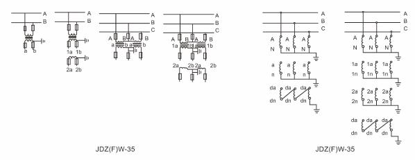
Installation Diagram
The JDZW-35KV voltage transformer must be securely mounted on a stable concrete foundation or steel structure using the provided fixing holes. Primary connection is typically made via overhead conductor or busbar, while secondary wiring is routed through the sealed terminal box. Maintain adequate electrical clearance and creepage distance per local regulations.
Outline Dimensions
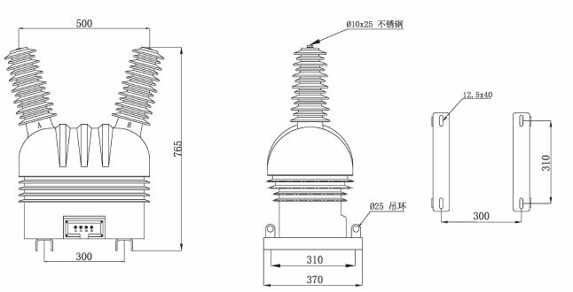
| Dimension | Value (mm) |
|---|---|
| Total height | 1250 |
| Base width | 320 x 320 |
| Mounting hole pattern | 260 x 260 |
| Bolt size | M16 |
| Primary terminal height | 1100 |
| phi of base holes | 18 |
Selection & FAQs
Selection Guide
- Select voltage ratio based on system nominal voltage (35kV) and required secondary voltage (100V for line-to-line, 100/â3 V for line-to-ground).
- Choose accuracy class per application: Class 0.2 for revenue metering, 0.5 for indication, or 6P for protection (note: JDZW-35 supports single-core configurations only).
- Calculate total rated burden (VA) by summing input impedance of connected meters, relays, and wiring losses at 100V.
- Confirm insulation level (40.5/95/200 kV) meets or exceeds system requirements based on grounding method and overvoltage exposure.
- For ground fault detection requiring residual voltage, consider JDZXW-35 variants insteadâJDZW-35 does not include an auxiliary winding.
- Specify altitude, pollution severity, or special environmental conditions during ordering for engineering validation.
Frequently Asked Questions
Q1: How do I correctly select between accuracy classes 0.2 and 0.5 for the JDZW-35 voltage transformer in a 35kV outdoor substation application?
Accuracy class selection for the JDZW-35 depends on the functional requirement of the secondary circuit. Class 0.2 is mandated by IEC 61869-3 and GB/T 20840.3 for revenue-grade energy metering where billing accuracy is critical; it guarantees a maximum ratio error of ±0.2% at 80–120% of rated voltage and burden. Class 0.5, with ±0.5% error under the same conditions, is suitable for general monitoring, SCADA voltage indication, or non-revenue metering. Note that the JDZW-35 provides only single-core configurations—so you cannot combine both classes in one unit. If your system requires simultaneous metering (0.2) and protection (6P), you must install separate VTs, as the standard JDZW-35 does not support multi-core or auxiliary windings for residual voltage.
Q2: Why can’t the JDZW-35 be used for ground-fault protection in unearthed or compensated neutral systems, and what alternative should I consider?
The JDZW-35 is a single-phase, line-to-ground connected voltage transformer without an auxiliary (tertiary) winding or open-delta configuration. In unearthed (IT) or resonant-earthed (Peterson coil) 35kV systems, ground-fault detection relies on measuring zero-sequence (residual) voltage, which requires either three single-phase VTs wired in open delta or a dedicated three-phase VT with a tertiary winding (e.g., JDZXW-35). The JDZW-35’s design only supports phase-to-ground voltage measurement for metering or indication. Attempting to derive residual voltage from a single JDZW-35 will yield incorrect or no fault signal. For such applications, specify the JDZXW-35 series, which includes an auxiliary winding rated for 100/3 V and meets 6P protection accuracy per IEC 61869-3.
Q3: What are the critical installation precautions to ensure long-term reliability of the JDZW-35 in high-humidity or coastal environments?
Although the JDZW-35’s fully enclosed epoxy resin casting offers inherent resistance to moisture, UV, and pollution (rated for IEC 60815 pollution severity level II), improper installation can compromise performance. Key precautions include: (1) Mounting on a stable, vibration-free foundation using M16 bolts through the 260×260 mm hole pattern to prevent mechanical stress on the brittle resin; (2) Ensuring primary conductor alignment avoids lateral tension on the 1100 mm-high terminal; (3) Sealing all unused cable entries in the metal terminal box with IP54-rated gland fittings to prevent salt-laden or humid air ingress; (4) Verifying creepage distance ≥25 mm/kV (i.e., ≥875 mm for 35 kV) based on local pollution maps—even though the unit is rated for level II, coastal zones may require additional silicone grease or RTV coating if operating near level III. Always perform a post-installation insulation resistance test (>1000 MΩ at 2500 V DC) before energization.
Q4: How should I interpret the insulation level “40.5/95/200 kV” for the JDZW-35, and why does it matter for my 35kV system design?
The insulation level notation “40.5/95/200 kV” per IEC 60071 defines three critical withstand values: Um = 40.5 kV (highest system voltage), LIPL = 95 kV (lightning impulse withstand voltage, peak), and ACSD = 200 kV (power frequency short-duration withstand voltage, RMS for 1 min). For a nominal 35 kV system (Um = 40.5 kV), this rating ensures compatibility with standard BIL (Basic Insulation Level) requirements. The 95 kV LIPL protects against switching and lightning surges, while the 200 kV ACSD confirms dielectric integrity during temporary overvoltages (e.g., ferroresonance or single-phase faults in non-effectively grounded systems). If your network uses fast transient suppressors or operates in areas with high lightning density, verify that the system’s expected surge profile does not exceed these limits—otherwise, consider overvoltage coordination studies or surge arresters rated ≤95 kV BIL.
Q5: What happens if the secondary winding of the JDZW-35 is left open-circuited while the primary is energized, and how can this be prevented?
Leaving the secondary circuit of the JDZW-35 open while the primary is energized causes the magnetic flux to saturate the core, inducing dangerously high voltages (several kV) across the open terminals due to uncontrolled magnetizing current. This can damage insulation, pose arc-flash hazards, and distort measurements. Per IEC 61869-3, all electromagnetic VT secondaries must be short-circuited or connected to a burden during operation. Prevention measures include: (1) Installing shorting links or automatic shorting blocks in the terminal box; (2) Using fused or breaker-protected secondary circuits with fail-safe design; (3) Training personnel to always apply grounding clamps to secondary terminals before disconnecting meters. Never rely solely on meter internal impedance as a burden—always verify total connected VA meets or exceeds the minimum specified (typically ≥25% of rated burden).
Q6: How do I calculate the total burden (VA) for the JDZW-35 to ensure accuracy compliance, and what are common pitfalls?
Total burden (in VA) is the sum of apparent power consumed by all devices connected to the secondary (meters, relays, transducers) plus wiring losses, calculated at the rated secondary voltage (100 V or 100/√3 V). For example, if connecting a kWh meter (10 VA), a voltage relay (5 VA), and 50 m of 2.5 mm² copper cable (resistance ≈0.35 Ω/m round-trip → I²R loss = (1 A)² × 35 Ω = 35 VA at 100 V), total burden = 10 + 5 + 35 = 50 VA. Common pitfalls include: (1) Ignoring cable impedance—especially in long runs (>20 m); (2) Assuming modern digital meters have negligible burden (many still draw 2–5 VA); (3) Exceeding the rated burden (75 VA for Class 0.2, 100 VA for Class 0.5), which degrades accuracy beyond tolerance. Always validate burden at 100% and 25% of rated load per IEC 61869-3 test protocols.
Q7: Can the JDZW-35 be customized for 60 Hz systems, higher altitudes, or different secondary voltages, and what are the technical trade-offs?
Yes, the JDZW-35 can be customized per factory engineering review. For 60 Hz operation, the core cross-section must be reduced (~17%) to maintain constant volts-per-turn and avoid saturation, which may slightly increase no-load losses but remains within thermal limits. For altitudes >1000 m, external insulation (creepage and clearance) must be derated per IEC 60071-2—typically requiring extended sheds or larger dimensions, though the epoxy resin body itself is unaffected. Secondary voltage options include 100 V (line-to-line systems) or 100/√3 V (line-to-ground); changing this affects turns ratio and requires recalibration. Note: Customizations impact lead time (+2–4 weeks) and cost (+10–20%), and may void standard type-test certificates unless re-certified. Always provide full system parameters (frequency, altitude, pollution, grounding method) during RFQ.
Q8: What maintenance checks and troubleshooting steps are recommended for JDZW-35 units after 5+ years of outdoor service?
While epoxy resin VTs like the JDZW-35 are largely maintenance-free, periodic inspection is advised after 5 years, especially in harsh environments. Recommended checks: (1) Visual inspection for UV-induced surface chalking, cracks, or tracking marks on the resin housing; (2) Terminal box seal integrity and corrosion on secondary terminals; (3) Insulation resistance test (>1000 MΩ at 2500 V DC between primary-secondary and ground); (4) Ratio and polarity verification using a portable VT tester at 20–100% of rated voltage—deviation >±0.5% for Class 0.5 units indicates core aging or winding issues. If moisture ingress is suspected (e.g., fogging inside terminal box), perform a dielectric dissipation factor (tan δ) test; values >0.5% at 10 kV suggest internal degradation. Replace immediately if physical damage, insulation failure, or accuracy drift beyond class limits is confirmed.