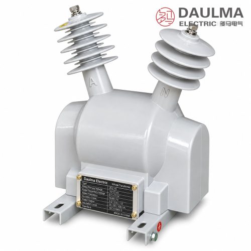
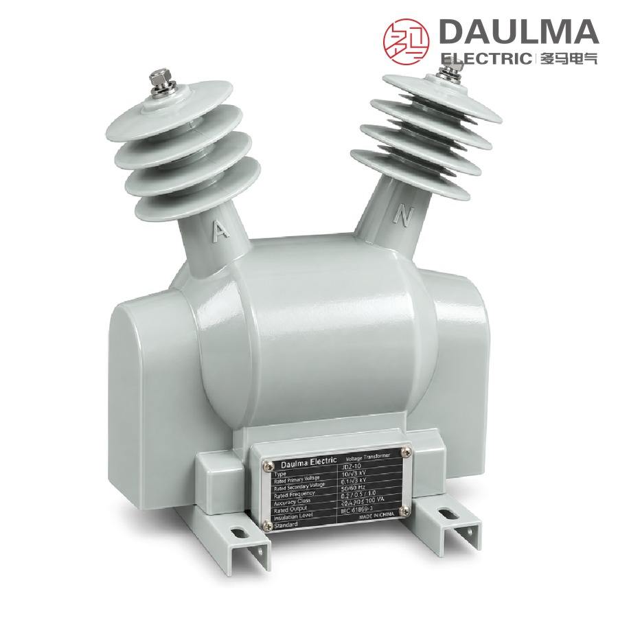
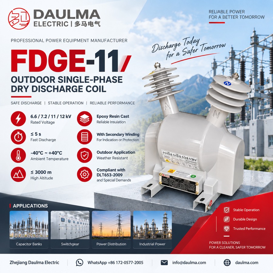
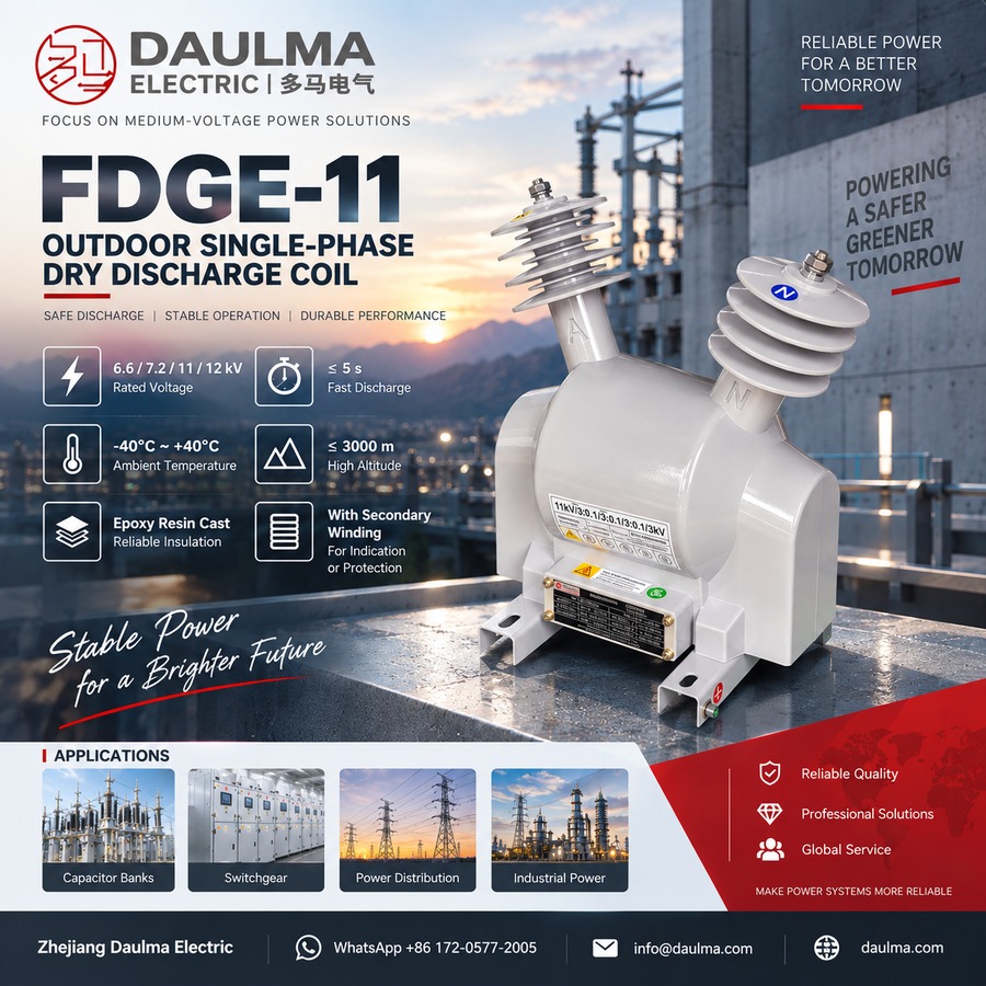
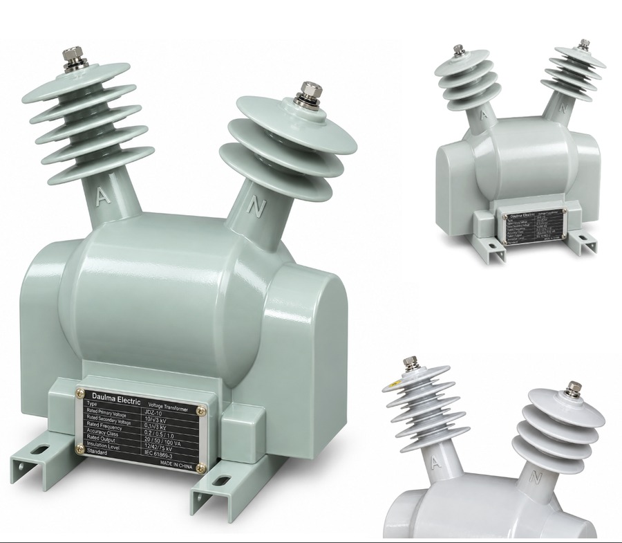
The FDGE11 outdoor dry type discharge coil is an epoxy resin vacuum-cast, single-phase, fully-enclosed outdoor product for AC power systems at 50Hz/60Hz with a rated voltage of 12kV and below. It is connected in parallel with the high-voltage shunt capacitor bank. When the capacitor group is disconnected from the system, the coil provides a defined discharge path that reduces the residual voltage of the capacitor bank to a safe value within five seconds, protecting operating personnel and downstream equipment.
The coil adopts a fully-enclosed post-type structure vacuum-cast with outdoor-grade epoxy resin, giving excellent arc resistance, UV resistance, anti-aging performance and long service life. During normal operation the secondary winding functions as a voltage indicator; where users require it, a residual voltage winding can be provided to deliver relay protection. The sealed secondary terminal box is both rain-proof and lightning-proof, making the unit compact, light-weight and maintenance-free — the ideal replacement for outdoor oil-immersed discharge coils.
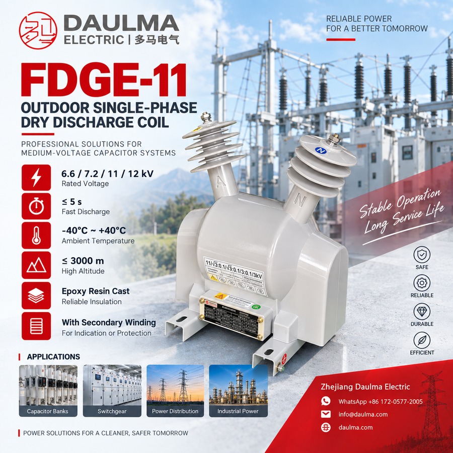
Key Ratings Snapshot
| Item | Value |
|---|---|
| System frequency | 50Hz / 60Hz |
| Rated primary voltage | 6.6/√3, 7.2/√3, 11/√3, 12/√3 kV |
| Rated secondary voltage | 0.1 kV |
| Accuracy class / rated output | 0.2 → 20VA; 0.5 → 50VA; 1 → 100VA |
| Discharge capacity | 1.7 / 2.5 / 3.4 Mvar |
| Rated insulation level | 7.2/32/60 kV; 12/42/75 kV |
| Residual discharge time | ≤ 5s to safe voltage |
| Surface creepage distance | > 420mm |
| Load power factor | cosφ 0.8 (lagging) |
| Phase / installation | Single phase / outdoor |
| Ambient temperature / altitude | -40℃ ~ +40℃ / ≤ 3000m |
| Standard | DL/T 653 |
Operating Function
The discharge coil is connected in parallel across the terminals of the high-voltage shunt capacitor bank. While the bank is energized the coil operates as a voltage transformer and its secondary winding supplies a proportional low voltage used for voltage indication. When the capacitor bank is switched off, the stored electrostatic energy of the capacitors discharges through the coil windings; the coil presents a controlled impedance path that drains the residual voltage to a safe level within five seconds. If a residual voltage winding is fitted, its output can drive a relay to provide unbalance or residual-voltage protection for the capacitor bank.
Construction and Design
The FDGE11 uses an outdoor fully-enclosed vacuum-cast post-type structure. Because the whole unit is vacuum-cast with outdoor-grade epoxy resin, it combines arc resistance, UV resistance, anti-aging performance and a long service life. The secondary terminals are fully enclosed, preventing induced lightning over-voltage as well as rain ingress. The unit is small in volume, light in weight, low in no-load loss and strong in over-voltage withstand capability; installation is convenient and no maintenance is required. It is the ideal product to replace outdoor oil-immersed discharge coils.
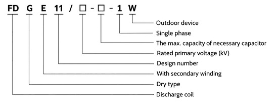
Model Designation
- FD — Discharge coil
- G — Dry type
- E — With secondary winding
- 11 — Design number
- / □ — Rated primary voltage, kV
- □ — Maximum matched capacitor capacity, Mvar
- – 1 — Single phase
- W — Outdoor device
Example: FDGE11/6.6/√3-1.7-1W denotes a dry-type outdoor fully-enclosed discharge coil with secondary winding, design No.11, rated primary voltage 6.6/√3 kV, matched capacitor capacity 1.7Mvar, single phase, outdoor device.
Technical Parameters
Service Conditions
- Installation position: Outdoor type
- Ambient temperature: -40℃ ~ +40℃
- Altitude: Not more than 3000m
- System frequency: 50Hz / 60Hz
- Atmosphere: No corrosive gas; no conducting or explosive dust
- Surface creepage distance: More than 420mm
Technical Data
| Type | Rated
voltage ratio (kV) |
Accuracy class
& rated secondary output (VA) |
Discharge
capacity (Mvar) |
Rated
insulation level (kV) |
||
|---|---|---|---|---|---|---|
| 0.2 | 0.5 | 1 | ||||
| FDGE11/6.6/√3-1.7-1W | 6.6/√3/0.1 | 20 | 50 | 100 | 1.7 | 7.2/32/60 |
| FDGE11/7.2/√3-1.7-1W | 7.2/√3/0.1 | 1.7 | 7.2/32/60 | |||
| FDGE11/11/√3-1.7-1W | 11/√3/0.1 | 1.7 | 12/42/75 | |||
| FDGE11/11/√3-2.5-1W | 11/√3/0.1 | 2.5 | 12/42/75 | |||
| FDGE11/11/√3-3.4-1W | 11/√3/0.1 | 3.4 | 12/42/75 | |||
| FDGE11/12/√3-1.7-1W | 12/√3/0.1 | 1.7 | 12/42/75 | |||
| FDGE11/12/√3-2.5-1W | 12/√3/0.1 | 2.5 | 12/42/75 | |||
| FDGE11/12/√3-3.4-1W | 12/√3/0.1 | 3.4 | 12/42/75 | |||
Standards
- DL/T 653 《Specification of discharge coils for high voltage parallel connection capacitor for order》
- The products accord with the standards of DL/T 653 and some special customer demands
- Load power factor: cosφ 0.8 (lagging)
- Surface creepage distance: more than 420mm
Installation & Wiring
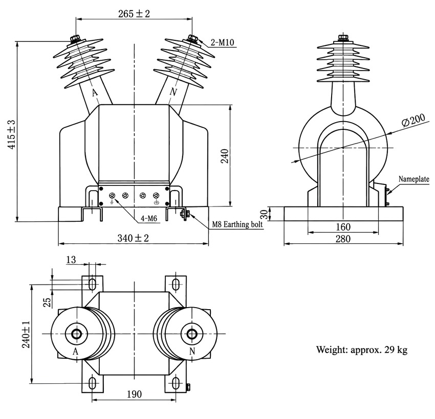
Installation Diagram
Overall dimensions (mm): height 415±3; top terminal spacing 265±2 with 2-M10 terminals; body height 240; base 340±2 (width) × 280 (length); footprint 240±1 × 190 with 13×25 mounting slots; body diameter Ø200; base thickness 30; secondary terminal board 4-M6; M8 earthing bolt; weight approx. 29 kg. Refer to the approved outline drawing before foundation and busbar work.
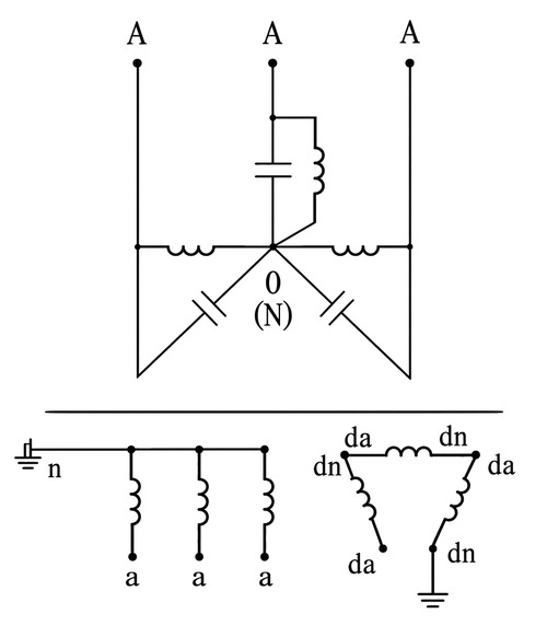
Wiring Diagram
The primary winding (terminal A) is connected between the busbar and the neutral/earth point of the high-voltage capacitor bank (terminal N). The secondary winding supplies voltage indication; where fitted, the residual voltage winding connects to the protection relay. Confirm terminal markings, polarity and earthing against the approved wiring drawing before energization.
Applications
- Outdoor HV shunt capacitor banks in substations and distribution networks (6.6-12kV)
- Reactive power compensation and power-factor correction installations
- Capacitor bank protection schemes requiring residual-voltage relay input
- Replacing outdoor oil-immersed discharge coils in pole-mounted and gable-frame banks
Selection & FAQs
Selection Guide
- State the rated primary voltage. Choose from 6.6/√3, 7.2/√3, 11/√3 or 12/√3 kV to match the capacitor bank system voltage.
- State the capacitor bank capacity (Mvar). Select the matched discharge capacity 1.7, 2.5 or 3.4 Mvar; do not order by model code alone.
- Confirm system frequency and secondary use. 50Hz or 60Hz; specify whether the secondary is for voltage indication only or whether a residual voltage winding is required for relay protection.
- Specify accuracy class and burden. 0.2 (20VA), 0.5 (50VA) or 1 (100VA) according to the connected metering/protection load.
- Confirm the outdoor environment. Ambient -40℃~+40℃, altitude ≤3000m, creepage distance >420mm; verify insulation level 7.2/32/60 or 12/42/75 kV.
FAQs
Q1: What is the FDGE11 discharge coil used for?
The FDGE11 is connected in parallel with a high-voltage shunt capacitor bank. After the bank is disconnected from the system it reduces the residual voltage on the capacitors to a safe level within five seconds, and its secondary winding provides voltage indication during normal operation.
Q2: What makes the FDGE11 suitable for outdoor installation?
The whole unit is vacuum-cast with outdoor-grade epoxy resin in a fully-enclosed post-type structure, giving arc resistance, UV resistance and anti-aging performance. It operates from -40℃ to +40℃ at altitudes up to 3000 m, with a surface creepage distance over 420 mm, and the sealed secondary terminal box is rain-proof and lightning-proof.
Q3: What is the difference between the FDGE11 and the FDGE8/FDGE9?
FDGE8 and FDGE9 are indoor discharge coils (-5℃~+40℃, altitude ≤1000 m), while the FDGE11 is an outdoor version with a post-type cast body and outdoor bushings, rated for -40℃~+40℃, altitude up to 3000 m and creepage distance over 420 mm, and for 50Hz/60Hz systems.
Q4: How do I read the model designation FDGE11/6.6/√3-1.7-1W?
FD = discharge coil, G = dry type, E = with secondary winding, 11 = design number, 6.6/√3 = rated primary voltage in kV, 1.7 = maximum matched capacitor capacity in Mvar, 1 = single phase, W = outdoor device.
Q5: How fast does the FDGE11 discharge the capacitor bank?
When the capacitor bank is switched off, the coil reduces the residual voltage to a safe level within five seconds under a load power factor of cosφ 0.8 (lagging), in line with DL/T 653.
Q6: Can special parameters be customized?
Yes. If the required parameters go beyond the ranges in the technical data table, they may be subject to an agreement between manufacturer and purchaser; voltage ratio, secondary voltage and residual-voltage winding options can be agreed at order.