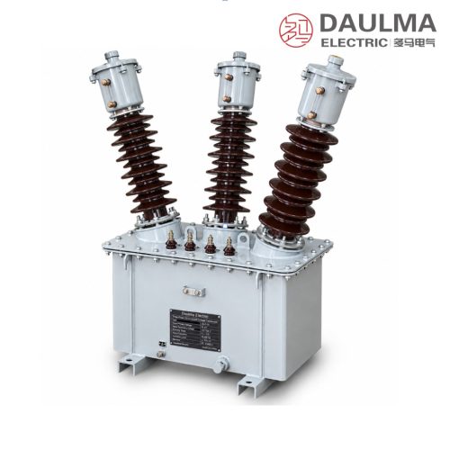
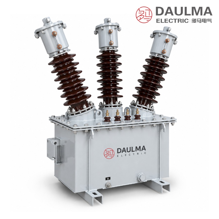
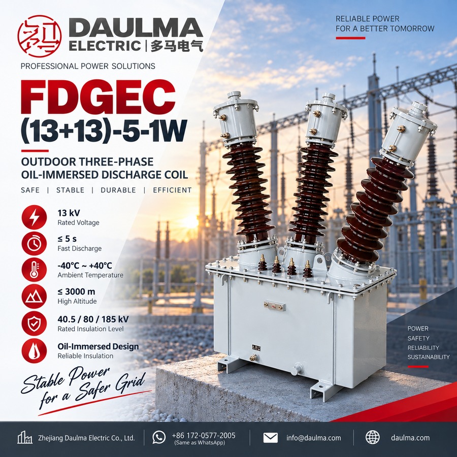
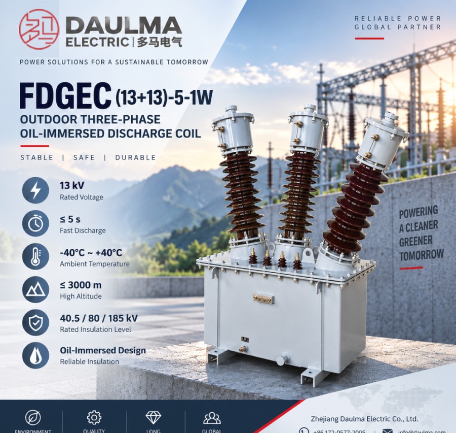
The FDGEC outdoor three-phase oil immersed discharge coil is a common-tank unit for AC power systems at 50Hz/60Hz. It is connected with the high-voltage shunt capacitor bank so that, when the bank is disconnected from the system, the coil provides a defined discharge path that reduces the residual voltage of the capacitors to a safe value within five seconds, protecting operating personnel and downstream equipment.
The three-phase core and winding assembly is installed in a sealed steel tank filled with mineral oil, and the primary terminals are brought out through three outdoor porcelain bushings. The primary winding is built in two sections of 13 kV each, matching the section voltage of the capacitor bank it serves. During normal operation the 13/0.1 kV secondary winding, accuracy class 0.5 with 50 VA output, functions as a voltage indicator and can also feed residual-voltage protection for the bank.
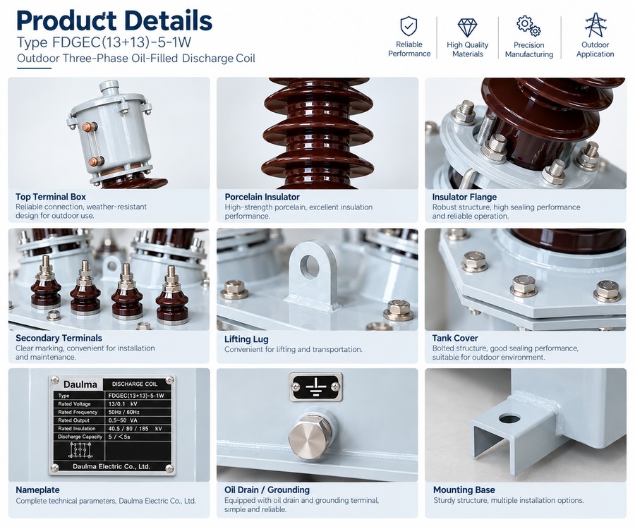
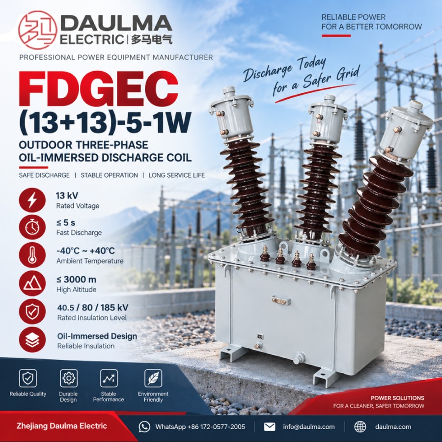
Key Ratings Snapshot
| Item | Value |
|---|---|
| System frequency | 50Hz / 60Hz |
| Number of phases | Three phase, common tank |
| Rated voltage ratio | 13 / 0.1 kV |
| Primary winding | Two sections of 13 kV, (13+13) |
| Accuracy class & rated output | 0.5 → 50VA |
| Discharge capacity | 5 Mvar |
| Rated insulation level | 40.5/80/185 kV |
| Residual discharge time | < 5s to safe voltage |
| Ambient temperature | -40℃ ~ +40℃ |
| Installation | Outdoor |
| Insulation medium | Mineral oil, sealed steel tank |
| Standards | GB50227-2017 and DLT653-2009, plus special customer demands |
Operating Function
While the capacitor bank is energized the discharge coil operates as a voltage transformer: its secondary winding supplies a proportional low voltage used for voltage indication or protection relays. When the bank is switched off, the stored electrostatic energy of the capacitors discharges through the two-section primary windings, and the residual voltage is drained to a safe level within five seconds. The 40.5/80/185 kV insulation level covers lightning-impulse and power-frequency withstand requirements of 35 kV class installations.
Construction and Design
The three phases share one gasketed steel tank, which makes the assembly compact compared with three separate single-phase units. Oil serves both as the insulation medium and the cooling medium, giving the unit strong over-voltage capability and a stable thermal rating. A secondary terminal box on the tank wall allows safe connection of the metering and protection circuits, and the tank is provided with an earthing bolt. The design conforms to GB50227-2017 and DLT653-2009 and can be built to special customer demands.
Technical Parameters
Service Conditions
- Installation position: Outdoor type
- Number of phases: Three phase, common tank
- Ambient temperature: -40℃ ~ +40℃
- System frequency: 50Hz / 60Hz
- Insulation medium: Mineral oil in sealed steel tank
- Atmosphere: No corrosive gas; no conducting or explosive dust
Technical Data
| Type | Rated voltage ratio (kV) | Accuracy class & rated output (VA) | Rated insulation level (kV) | Discharge capacity (Mvar) |
|---|---|---|---|---|
| FDGEC(13+13)-5-1W | 13/0.1 | 0.5-50 | 40.5/80/185 | 5 / <5s |
Standards
- The products accord with the standards of GB50227-2017, DLT653-2009 and some special demands
- Rated frequency: 50Hz / 60Hz
- Rated insulation level: 40.5/80/185 kV
Installation & Wiring
Installation Diagram
The unit stands on a flat foundation with the tank base level; allow clearance around the tank for bushing creepage distances and for access to the secondary terminal box. The three primary bushings connect to the capacitor bank and the busbar or neutral point as per the approved circuit diagram; the tank is connected to the earthing grid through the earth bolt. Refer to the approved outline drawing for foundation and busbar work.
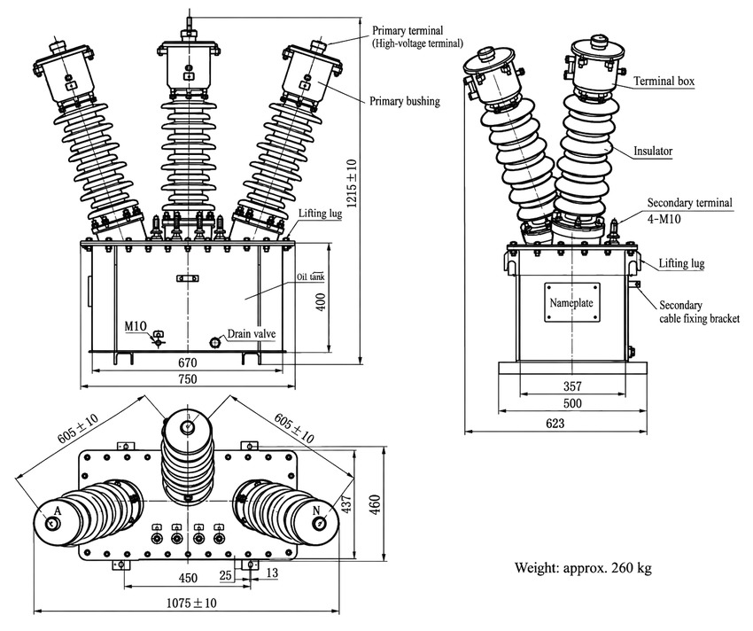
Key Outline Dimensions
- Overall height: 1215±10 mm (primary bushings included, three-phase V-arrangement)
- Width over bushings: 1075±10 mm; bushing pitch 605±10 mm
- Tank: 400 mm high; base 750 mm front-to-back × 623 mm side-to-side
- Mounting: hole pitch 670 × 500 mm (detail 450 mm, slot 25 × 13 mm)
- Primary terminals: high-voltage terminal on each bushing; secondary terminals: 4-M10 with cable fixing bracket
- Earthing bolt: M10; drain valve on tank wall; lifting lugs on lid and tank
- Weight: approx. 260 kg
Wiring Diagram
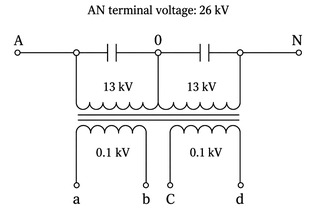
The two-section primary windings are connected to the designated sections of the capacitor bank as shown in the wiring diagram. The 13/0.1 kV secondary winding supplies voltage indication and residual-voltage protection circuits. Confirm terminal markings, polarity and earthing against the approved wiring drawing before energization.
Applications
- Outdoor HV shunt capacitor banks in 35 kV class substations and distribution networks
- Reactive power compensation and power-factor correction installations
- Capacitor bank protection schemes requiring secondary winding for indication or relays
- Double-section capacitor bank arrangements matched to (13+13) kV winding duty
Selection & FAQs
Selection Guide
- State the system voltage class. The standard type covers 35 kV class banks with insulation level 40.5/80/185 kV.
- State the capacitor bank capacity (Mvar). The standard unit covers a 5 Mvar discharge duty with discharge time under five seconds.
- Confirm the bank wiring. The (13+13) two-section primary winding must match the bank section arrangement.
- Confirm system frequency. 50Hz or 60Hz.
- Choose the secondary duty. 13/0.1 kV, class 0.5, 50VA, for indication and/or relay protection.
FAQs
Q1: What is the FDGEC discharge coil used for?
The FDGEC is connected with a high-voltage shunt capacitor bank. After the bank is disconnected from the system it reduces the residual voltage on the capacitors to a safe level within five seconds, and its secondary winding provides voltage indication or relay protection during normal operation.
Q2: How is the FDGEC different from the single-phase FDE?
The FDGEC is a three-phase common-tank oil immersed unit with a 40.5/80/185 kV insulation level for 35 kV class capacitor banks, rated 5 Mvar with a 13/0.1 kV ratio. The FDE is a single-phase tank-type unit at 11/√3 kV with a 12/42/75 kV insulation level and 4 Mvar duty. Both discharge the bank to a safe voltage within five seconds.
Q3: What does the (13+13) in the model designation FDGEC(13+13)-5-1W mean?
The primary winding is built in two sections of 13 kV each, matching the section voltage of the capacitor bank it serves. The 5 denotes the 5 Mvar discharge rating and W denotes the outdoor design; the unit is rated 13/0.1 kV with a 5 s discharge time.
Q4: What is the difference between oil immersed and dry type discharge coils?
An oil immersed coil uses mineral oil in a sealed steel tank as insulation and cooling medium, a time-tested outdoor construction with strong over-voltage capability. A dry type coil (e.g. FDGE11) is vacuum-cast with epoxy resin, is completely oil-free and needs no oil level checks. Both types discharge the capacitor bank to a safe voltage within five seconds.
Q5: How fast does the FDGEC discharge the capacitor bank?
The residual voltage is reduced to a safe level in less than five seconds at a discharge duty of 5 Mvar, in accordance with GB50227-2017 and DLT653-2009.
Q6: Can special parameters be customized?
Yes. If the user’s data go beyond the ranges listed in the technical data table, they may be subject to an agreement between manufacturer and purchaser; voltage ratio, secondary output and insulation level can be agreed at order.