Overview
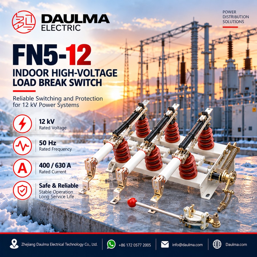
The FN5-12 series is an indoor AC high voltage load switch and load switch–fuse combination unit for three-phase 50 Hz systems rated 12 kV. Fully type-tested and proven in long-term service, it meets IEC 420 and GB 3804 and provides the three operating positions of switching, isolation and earthing in one compact, light frame for 10 kV power distribution.
It may be used on its own as a load switch or combined with current-limiting fuses to protect distribution transformers, and its design effectively prevents open-phase operation of the equipment. Rated at 400 A or 630 A with 12.5 / 20 kA short-time withstand current, it is widely applied in ring-main units and box-type substations.
Model Designation
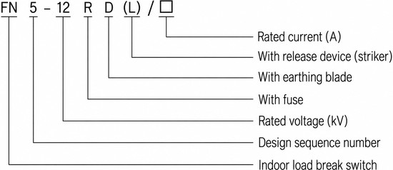
FN 5 – 12 R D (L) / □
- FN – Indoor load switch
- 5 – Design sequence number
- 12 – Rated voltage (kV)
- R – With fuse
- D – With earthing switch
- (L) – With trip device (striker)
- □ – Rated current (A)
Construction
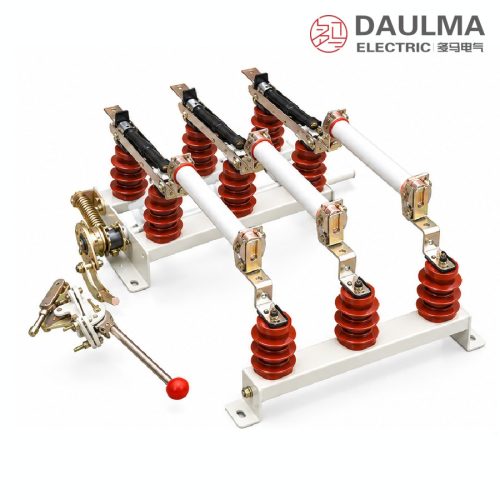
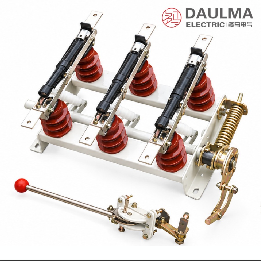
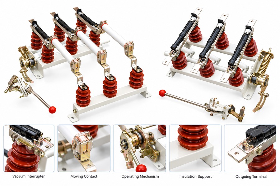
The FN5-12 is built on a steel base frame carrying support insulators, the moving and fixed contacts, arc-quenching (fuse) tubes and guide plates. The open/close mechanism drives the three-position switching, while a built-in interlock ties the load switch, earthing switch and fuse assembly together to prevent maloperation, and a trip (striker) device lets the fuses open the switch on fault.
The unit can be operated with a CS6-1 type operating mechanism linked through a bent connector and welded steel pipes (user-supplied). Its compact, lightweight structure and clear on-off-earth indication make it suitable for metal-enclosed ring-main and box substation panels.
Technical Parameters
Main Technical Parameters
| Item | Unit | 400 A frame | 630 A frame |
|---|---|---|---|
| Rated voltage | kV | 12 | 12 |
| 1-minute power-frequency withstand voltage | kV | 42 | 48 |
| Rated current | A | 400 | 630 |
| 4 s short-time (thermal) withstand current | kA | 12.5 | 20 |
| Peak withstand (dynamic) current | kA | 31.5 | 50 |
| Rated breaking (load) current | A | 400 | 630 |
| Short-circuit making current (peak) | kA | 31.5 | 50 |
Fuse Rated Parameters
| Model | Rated voltage | Rated current | Fuse-link ratings |
|---|---|---|---|
| SDLA*J | 12 kV | 50 A | 6.3, 10, 16, 20, 25, 31.5, 40 A |
| SFLA*J | 12 kV | 100 A | 50, 63, 71, 80, 100 A |
| SKLA*J | 12 kV | 125 A | 125 A |
Service Conditions
- Ambient temperature: −25 °C to +40 °C
- Altitude: ≤ 1000 m
- Air relative humidity: daily average ≤ 95%, monthly average ≤ 90%
- Surrounding air free from corrosive or flammable gas and obvious water-vapour contamination
- No frequent or severe vibration
Installation & Wiring
Installation Diagram
The FN5-12 is an indoor panel-mounted unit supplied in two frames — the bare load switch and the version with the CS6-1 operating mechanism linkage. Mount it vertically on a flat panel, verify the fixing-hole pattern and phase clearances against the outline drawing, and provide adequate operating clearance for the mechanism and the bent connector / welded steel pipes (user-supplied). All primary and secondary connections must comply with local utility standards.
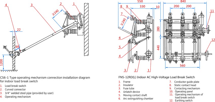
Outline & Mounting Dimensions
| Item | Unit | Value |
|---|---|---|
| Overall width (front view) | mm | 840 |
| Base / panel mounting width | mm | 560 |
| Phase (pole) spacing | mm | 200 |
| Side-view depth | mm | 550 |
| Side-view inner section | mm | 330 |
| Upper frame height | mm | 280 |
| Lower frame height | mm | 440 |
| Terminal / insulator clearance | mm | ≥ 240 |
| CS6-1 operating handle height | mm | 1200 |
The CS6-1 operating mechanism is linked to the load switch through a curved connector and 3/4” welded steel pipe (user-supplied).
Selection & FAQs
Selection & Ordering Guide
When specifying the FN5-12, confirm: rated current (400 A or 630 A frame), whether the earthing switch (D) and trip device (L) are required, the fuse model and fuse-link rating matched to the protected transformer, and the operating-mechanism type (CS6-1 or other).
FAQ
- What is the difference between the load switch and the fuse combination?
- Used alone, the FN5-12 makes and breaks load current. Combined with current-limiting fuses (suffix R), the unit also interrupts short-circuit faults, giving compact and economical protection for distribution transformers in ring-main and box substations.
- What do the three positions mean?
- The switch provides switching, isolation and earthing in one frame. The built-in interlock ties these positions together so the circuit cannot be earthed while live and cannot be re-closed while earthed, protecting maintenance personnel.
- What is the trip (striker) device for?
- The optional trip device (suffix L) is struck by the fuse-link striker when the fuse blows, opening the load switch and preventing dangerous open-phase operation after a single fuse has cleared.
- How do I choose the fuse?
- Match the fuse to the protected transformer: SDLA*J (50 A), SFLA*J (100 A) or SKLA*J (125 A), each with the fuse-link ratings listed in the parameter table. Select the link rating just above the transformer full-load current.
- Which standards does it comply with?
- The FN5-12 series is type-tested to IEC 420 (AC high voltage switch-fuse combinations) and GB 3804 (3–63 kV AC high voltage load switches).
- What service conditions apply?
- Ambient temperature −25 to +40 °C, altitude up to 1000 m, daily humidity ≤ 95% / monthly ≤ 90%, air free from corrosive or flammable gas, and no frequent severe vibration.