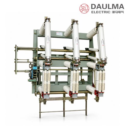
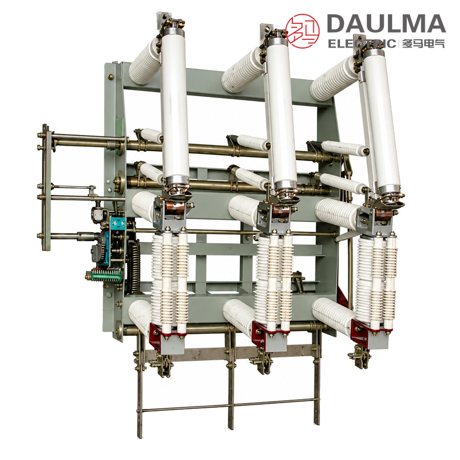
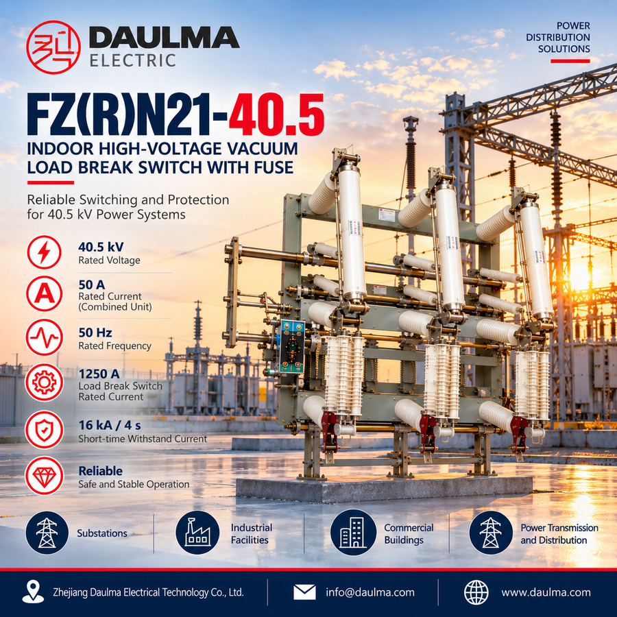
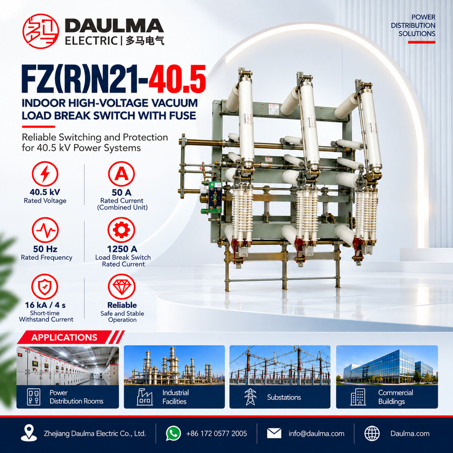
The FZN21-40.5 indoor high-voltage AC vacuum load break switch and the FZRN21-40.5D switch-fuse combination unit are built for 35 kV box-type substations in networks of 40.5 kV at 50 Hz, and either unit can also be used as a standalone switching unit.
The load break switch makes and breaks load and overload current at 1250 A and needs no maintenance between services; in the combination unit the series striker-type fuse clears short-circuit current at 20 kA.
Model Designation
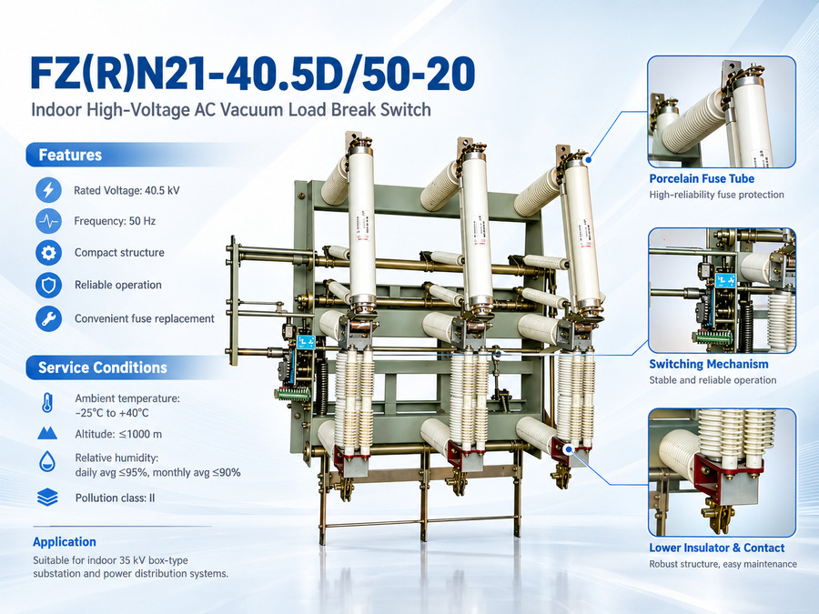
The designation of the combination unit reads FZRN21-40.5D/50-20, letter by letter:
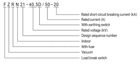
- F: Load break switch
- Z: Vacuum
- R: With fuse
- N: Indoor
- 21: Design sequence number
- 40.5: Rated voltage, kV
- D: With earthing switch
- 50: Rated current, A
- 20: Rated short-circuit breaking current, kA
Without the R the designation FZN21-40.5 describes the load break switch on its own, rated 1250 A, which carries the load and overload duties and relies on upstream protection for fault current.
Construction and Operation
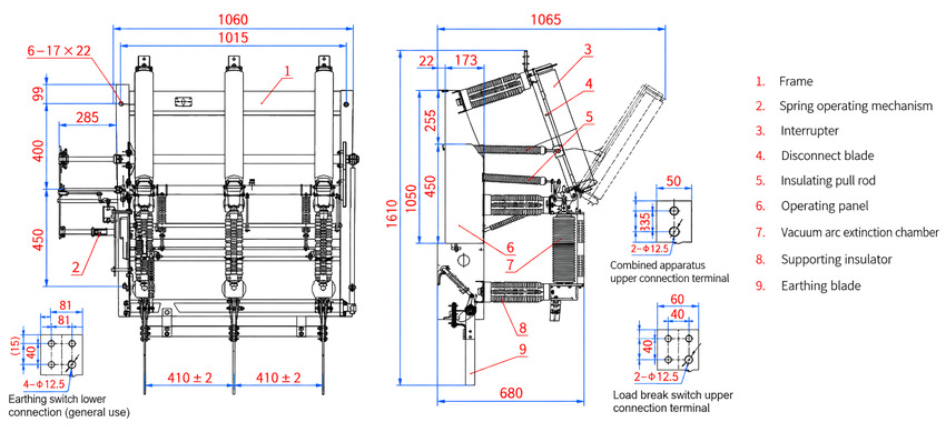
The three poles stand on a common steel frame: the spring operating mechanism drives the disconnect blade and the earthing blade through the insulating pull rod, the vacuum arc extinction chamber interrupts the circuit, and the operating panel at the front shows the position of each. The disconnect blade gives a visible isolation gap and the earthing blade bonds the de-energised side before maintenance.
The vacuum chamber carries current only at the instant of closing and opening, which is what allows the switch to be offered as a maintenance-free unit with a mechanical life of 10000 operations.
Fuse Handling and Maintenance
The striker of the series fuse acts on the release device, so a blown fuse is reported at the switch instead of being left to protection alone. The fuse compartment is reached only after the circuit is isolated and earthed, and the fuse is replaced one-for-one with the same rated type.
What remains to be maintained is the mechanism, the interlocks and the insulation, and the chamber itself once contact wear reaches the permissible 3 mm; no oil or gas top-up is needed.
Technical Parameters
Service Conditions
- Ambient temperature: +40℃ upper, -25℃ lower
- Altitude: Not more than 1000 m
- Relative humidity: Daily average not more than 95%, monthly average not more than 90%
- Seismic intensity: Not more than 8 degrees
- Site condition: No fire, explosion hazard, chemical corrosion or violent vibration
- Pollution level: II
Electrical Performance Parameters
| No. | Item | Unit | Combined unit FZRN21-40.5D | Load break switch FZN21-40.5 |
|---|---|---|---|---|
| 1 | Rated voltage | kV | 40.5 | |
| 2 | Rated frequency | Hz | 50 | |
| 3 | Rated short-time withstand current (4 s) | kA | 16 | |
| 4 | Rated current | A | 50 | 1250 |
| 5 | Rated breaking current of active load | A | / | 1250 |
| 6 | Rated closed-loop breaking current | A | / | 1250 |
| 7 | Rated peak withstand current | kA | / | 40 |
| 8 | Rated short-circuit breaking current | kA | 20 | / |
| 9 | Rated cable charging current | A | / | 21 |
| 10 | 1 min power-frequency withstand voltage (vacuum gap, phase-to-phase and phase-to-earth / across the isolation gap) | kV | 95/110 | |
| 11 | Lightning impulse withstand voltage (vacuum gap, phase-to-phase and phase-to-earth / across the isolation gap) | kV | 185/215 | |
| 12 | 1 min power-frequency withstand voltage of control and auxiliary circuits | kV | 2 | |
| 13 | Mechanical life | operations | 10000 | |
| 14 | Permissible wear of the vacuum chamber contacts | mm | 3 | |
| 15 | Manual operating torque | N·m | Not more than 250 | |
Mechanical Performance Parameters
| No. | Item | Unit | Value |
|---|---|---|---|
| 1 | Contact gap | mm | 17±1 |
| 2 | Contact over-travel | mm | 5±1 |
| 3 | Average closing speed | m/s | 0.6±0.2 |
| 4 | Average opening speed | m/s | 1.5±0.2 |
| 5 | Opening and closing inconsistency of the three poles | ms | ≤2 |
| 6 | Closing bounce time of the contacts | ms | ≤3 |
| 7 | Clearance between live parts and to earth | mm | ≥300 |
| 8 | Main circuit resistance (excluding the fuse) | μΩ | Not more than 150 |
Installation & Wiring
Installation and Commissioning
The unit is bolted to the cubicle frame through the six 17 by 22 mm slots, the closed, open and earthed positions and the interlocks are checked on all three poles, the specified striker-type fuse is fitted with its striker engaging the release device, and the main circuit resistance and the clearances are measured before energisation.
Outline Dimensions
- Front view: overall width 1060 mm with 1015 mm between the outer frames, pole spacing 410 ± 2 mm marked twice, and vertical steps of 99 mm, 285 mm, 400 mm and 450 mm.
- Mounting slots: six slots of 17 by 22 mm on the frame.
- Side view: 1065 mm over the top, with steps of 22 mm and 173 mm, vertical dimensions of 255 mm, 450 mm and 1050 mm, an overall height of 1610 mm and 680 mm at the base.
- Terminals: the lower connection is drilled 4 holes of 12.5 mm and the upper connection 2 holes of 12.5 mm; the dimension marked (15) applies only where the earthing switch is fitted.
- Panel details: the outline drawing carries the complete dimension set; request the drawing for panel cut-outs and busbar drilling.
Component Reference
The item numbers below follow the outline and installation drawing of the series:
- Frame
- Spring operating mechanism
- Interrupter
- Disconnect blade
- Insulating pull rod
- Operating panel
- Vacuum arc extinction chamber
- Supporting insulator
- Earthing blade
Applications
- Indoor 35 kV box-type substations and package distribution stations
- Distribution networks of 40.5 kV at 50 Hz for load control and short-circuit protection
- Transformer feeders protected by the switch-fuse combination unit
- Oil-free installations that are not opened for overhaul between services and switch frequently
Selection & FAQs
Selection Guide
- Choose the switch or the combination unit. The FZN21-40.5 carries 1250 A of load current and relies on upstream protection for faults; transformer feeders in a 35 kV box-type substation normally take the FZRN21-40.5D unit, where the striker-type fuse clears short-circuit current at 20 kA and the loss of a phase is signalled at the switch.
- Check the short-time duty first. 16 kA for 4 s with a 40 kA rated peak withstand sets the busbar, the cable sizing and the upstream protection coordination; verify both against the network before ordering.
- Confirm the insulation level for the 40.5 kV network. The unit is rated 95/110 kV at 1 min power frequency and 185/215 kV lightning impulse, with 2 kV across the control and auxiliary circuits and a clearance of not less than 300 mm between live parts and to earth.
- Work out the cable and transformer duties. The switch breaks 21 A of cable charging current and 1250 A of active load and closed-loop current, so the same frame covers both cable network loops and direct transformer feeders.
- Compare with the rest of the range. For 40.5 kV outdoors on a pole or in a box, take the FZW-40.5; where the network is 12 kV, the FZN21A-12D is the same family at the lower voltage, and the FZN25-12DG covers 630 to 1250 A at 12 kV.
FAQs
Q1: What is the FZN21-40.5 used for?
It is an indoor three-phase vacuum load break switch for networks of 40.5 kV at 50 Hz, built for the 35 kV side of box-type substations. It makes and breaks load current and overload current, isolates the circuit through a visible gap on the disconnect blade and earths the de-energised side with the earthing blade. The FZRN21-40.5D combination unit adds a striker-type fuse so the same frame also clears short-circuit current at 20 kA.
Q2: Why does the page say 40.5 kV and 35 kV at the same time?
Both are correct and describe different things. 40.5 kV is the rated voltage of the switchgear, which is the highest voltage the equipment is designed to carry, while 35 kV names the system it is built for, namely the 35 kV side of a box-type substation. Switchgear rated 40.5 kV is the standard selection for a 35 kV network because it leaves margin for the operating voltage of that network.
Q3: How do I read FZRN21-40.5D/50-20?
F is the load break switch, Z the vacuum medium, R indicates the fuse is combined, N that the unit is for indoor use, 21 the design sequence number, 40.5 the rated voltage in kV, D that an earthing switch with making capacity is fitted, 50 the rated current of the combination unit in A and 20 the rated short-circuit breaking current in kA. Without the R, FZN21-40.5 is the switch on its own at 1250 A.
Q4: What is the difference between this indoor 40.5 kV unit and the FZW-40.5?
Both work at 40.5 kV and interrupt in a vacuum chamber, but they serve different installations. The FZW-40.5 is an outdoor isolating vacuum load break switch built to stand on a pole or in an outdoor box with weatherproof insulation. This FZN21-40.5 is an indoor unit for the switchgear compartment of a 35 kV box-type substation, with a 1250 A frame, 16 kA for 4 s and a combination-unit fuse. Choose the outdoor type where the switch is exposed to weather, and this one where it sits inside a cubicle.
Q5: How does it compare with the 12 kV members of the same family?
The design and the interrupting medium are the same, the voltage class is not. The FZN21A-12D is the 12 kV version of this series with a 630 A frame, and the FZN25-12DG is another indoor 12 kV vacuum unit. This FZN21-40.5 raises the rated voltage to 40.5 kV, the insulation levels to 95/110 kV power frequency and 185/215 kV lightning impulse, and the frame current to 1250 A, so it cannot be substituted for a 12 kV unit or the other way round.
Q6: Is the load break switch really maintenance-free, and how is the fuse changed?
The load break switch is designed to need no maintenance between services: the contacts work inside a sealed vacuum chamber, so there is no oil, gas or contact top-up, and the mechanical life is 10000 operations. What remains is periodic checking of the mechanism, the interlocks and the main circuit resistance, and replacement of the chamber when contact wear reaches the permissible 3 mm. On the combination unit the striker-type fuse is reached only after the circuit is isolated and earthed, and it is replaced one-for-one with the same rated type so the striker still drives the release device.