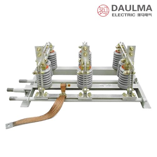
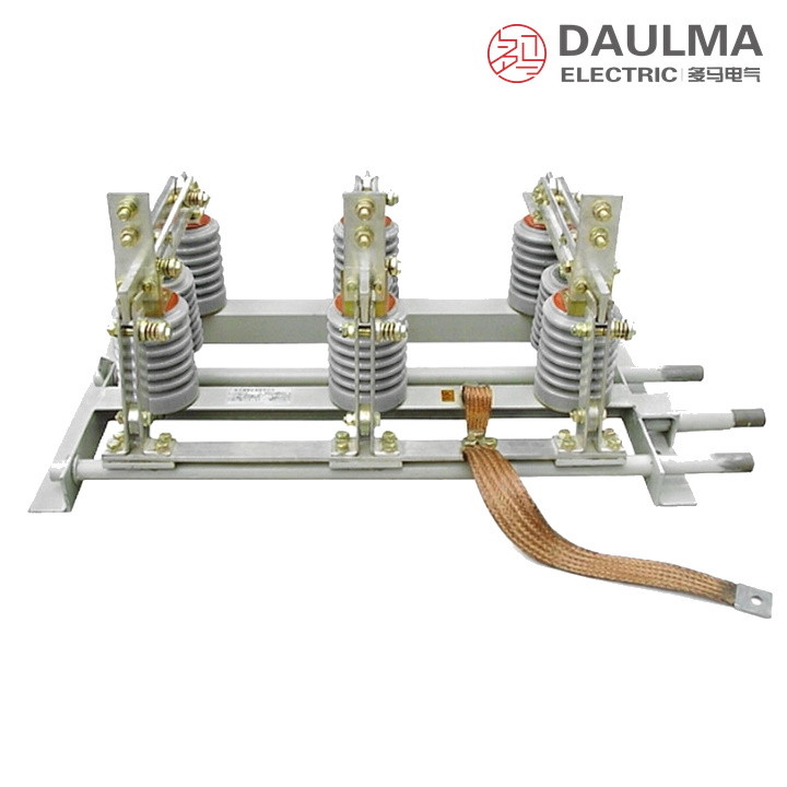
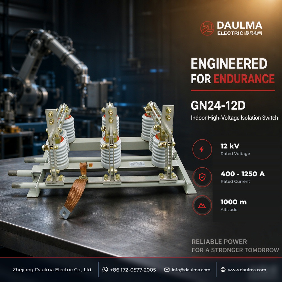
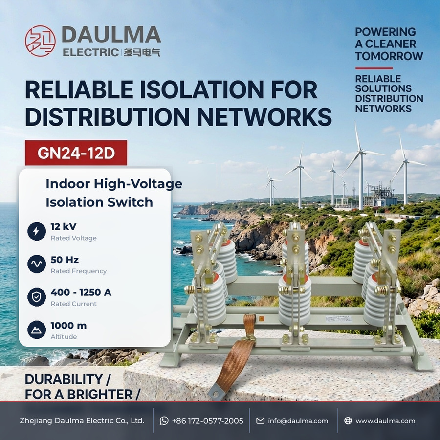
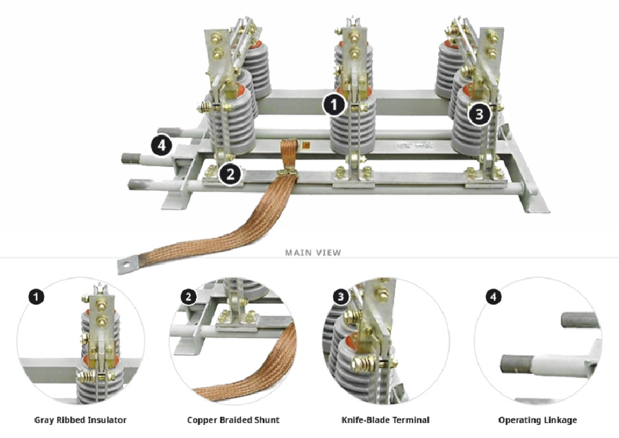
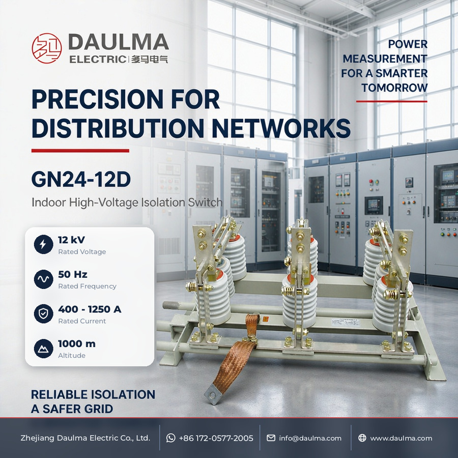
The GN24-12D is an indoor high-voltage disconnector for three-phase AC 50 Hz power systems. The catalogue describes the series as a device of rated voltage 10 kV while its type designation carries the figure 12 for the rated voltage; both are reproduced here as printed, and the rating of the delivered switch is the one stated on its nameplate. The main blades and the earthing knife are assembled on one common frame, so a single cubicle unit provides both the isolation and the earthing of a de-energised circuit.
The series is built in two earthing arrangements. Types with the Q suffix are the full-service versions, in which the moving or the stationary contact side is earthed, the main disconnector and the earthing knife sharing one frame, with type 1 operated from the left and type 2 from the right and a live-voltage indicator fitted on request. The SD types earth both the moving and the stationary contact sides with two earthing sets on the same frame, one of which may be operated separately or both by a single mechanism, and either contact side, or both, may be changed to wall bushings for penetration through the cubicle wall.
Model Designation
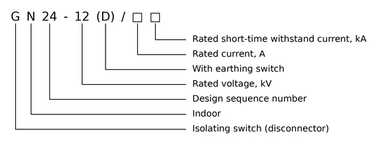
The type is designated G N24-12 (D)/□□ and decoded as follows:
- G — isolating switch (disconnector)
- N — indoor
- 24 — design sequence number
- 12 — rated voltage, kV
- (D) — with earthing switch
- □ — rated current, A
- □ — rated short-time withstand current, kA
In the type designations used in the overview, the suffix C marks the wall-bushing version and Q the full-service version, while S in GN24-12SD denotes the arrangement with two earthing sets.
Construction and Operation
The main disconnector and the earthing knife share one common frame, so a single cubicle assembly provides isolation and then earthing of a de-energised circuit. Type 1 is operated from the left and type 2 from the right. The Q types earth the moving or the stationary contact side; the SD types earth both sides through two earthing sets, worked separately or together by one mechanism, and either contact side, or both, may be changed to wall bushings to give the C version for penetration through the cubicle wall. A voltage-presence indicator is available on the Q types. As a disconnector it makes and breaks circuits under voltage but without load and provides the visible break; it has no load or short-circuit breaking capability.
Technical Parameters
Normal Service Conditions
- Altitude: 1000 m
- Ambient air temperature: the catalogue lists this condition without printing a limiting value; the ambient temperature range follows the ordering technical conditions
- Relative humidity of the surrounding environment: daily average value not more than 95%, monthly average value not more than 90%
- Seismic intensity: not above intensity 8
- Installation site: free from fire and explosion hazard, severe pollution, chemical corrosion and violent vibration
Rated Data of the Series
Installation & Wiring
Installation and Mounting
Bolt the complete frame to the cubicle structure on the 700 mm span through the 700 × 300 mm hole pattern, connect the conductors to the terminals, and couple the mechanism to the main blade shaft and the earthing shaft on the side given by type 1 or type 2. Check the full travel of both knives before energising.
Outline and Installation Dimensions
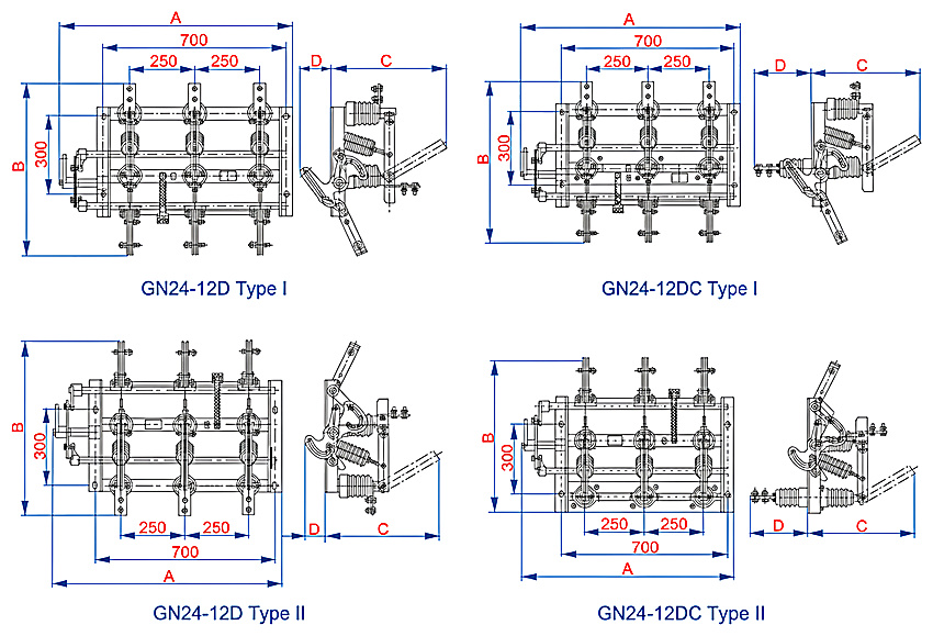
Fixed dimensions (mm): mounting span 700, phase spacing 250 + 250, frame dimension 300 and mounting holes 700 × 300. Four arrangements are drawn: GN24-12D type I and type II and the corresponding C versions.
The model column of the catalogue repeats GN24-12D type I for three rows with different values and does not state the difference; the rows are reproduced as printed, and the applicable frame must be confirmed from the order code.
| Model | 400 A / 630 A | 1000 A | 1250 A | Mounting holes (mm) | |||||||||
|---|---|---|---|---|---|---|---|---|---|---|---|---|---|
| A | B | C | D | A | B | C | D | A | B | C | D | ||
| GN24-12D I | 890 | 660 | 450 | 125 | 890 | 690 | 480 | 125 | 890 | 700 | 500 | 125 | 700 × 300 |
| GN24-12D II | 890 | 660 | 450 | 125 | 890 | 690 | 480 | 125 | 890 | 700 | 500 | 125 | |
| GN24-12D I | 890 | 660 | 450 | 240 | 890 | 690 | 480 | 350 | 890 | 700 | 500 | 350 | |
| GN24-12D II C | 890 | 660 | 450 | 240 | 890 | 690 | 480 | 350 | 890 | 700 | 500 | 350 | |
| GN24-12D I | 920 | 780 | 450 | 125 | 920 | 790 | 480 | 125 | 920 | 790 | 500 | 125 | |
| GN24-12D II C | 920 | 780 | 450 | 240 | 920 | 790 | 480 | 350 | 920 | 790 | 500 | 350 | |
Applications
- Isolation and earthing of indoor feeder, transformer and busbar circuits during inspection and maintenance
- Cubicles where the earth connection is made with the same operator as the isolation
- Left-hand or right-hand mechanism position according to the panel layout
- Wall-bushing C version for circuits taken through the cubicle or panel wall
- Full-service Q version where a voltage-presence indication is required
Selection & FAQs
Selection Guide
- Choose the earthing arrangement first: one earthed contact side for the standard frame, or both sides with the SD types.
- Select type 1 or type 2 according to the side on which the mechanism can be operated in the cubicle.
- Pick the frame tabulated for the current rating of the circuit among the 400 A, 630 A, 1000 A and 1250 A dimensions.
- Order the C wall-bushing version where the circuits pass through the panel or cubicle wall.
- Specify the Q full-service version and the voltage-presence indicator for severe or compact cubicles.
Frequently Asked Questions
Q1: What does the type designation GN24-12 (D) mean?
G is the isolating switch and N the indoor place of use; 24 is the design sequence number and 12 the rated voltage in kV, while D indicates that the switch is supplied with an earthing knife. The two fields after the slash give the rated current in A and the rated short-time withstand current in kA.
Q2: What is the difference between the D and the SD versions?
The D version carries one earthing knife on the moving or the stationary contact side, whereas the SD version carries two earthing sets on the same frame so that both contact sides can be earthed; one set can be operated on its own or both through a single mechanism.
Q3: Can this disconnector interrupt load or short-circuit current?
No. It makes and breaks circuits under voltage but without load and provides the visible break for isolation. Load and short-circuit currents are interrupted by the associated circuit breaker, and the earthing knife may only be closed after the circuit has been isolated and proved de-energised.
Q4: What do the suffixes 1, 2, C and Q indicate?
Type 1 is operated from the left side and type 2 from the right side of the frame. C marks the wall-bushing version for penetration through the cubicle wall, and Q the full-service version, to which a voltage-presence indicator can be attached on request.
Q5: What are the service conditions?
Altitude of 1000 m, relative humidity with a daily average value not more than 95% and a monthly average not more than 90%, seismic intensity not above 8, and a site free from fire and explosion hazard, severe pollution, chemical corrosion and violent vibration. The catalogue lists the ambient temperature without a value, so it is fixed by the ordering conditions.
Q6: Where do I find the rated current and withstand values?
This catalogue page gives no rated-parameter table, so the electrical data are taken from the type designation and the ordering technical agreement and are stated on the nameplate; the outline dimensions of the four frames are tabulated on this page. For a comparable indoor disconnector without an earthing knife see our GN19-12 three-pole disconnector, and the whole range is listed under disconnectors.