Overview
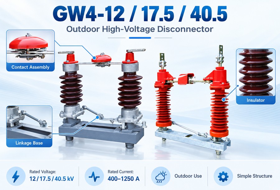
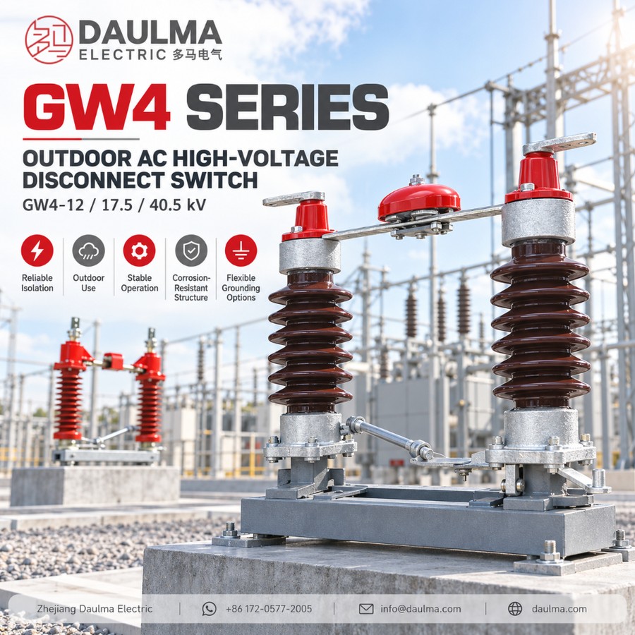
The GW4 is a double-post, horizontal-rotation outdoor AC high voltage disconnector for three-phase 50 Hz networks rated 12, 17.5 and 40.5 kV. It opens and closes lines under voltage but without load and, with the associated circuit breaker, provides a clearly visible insulating break for safe isolation; it cannot break load or short-circuit current.
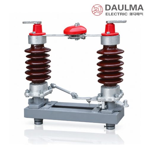
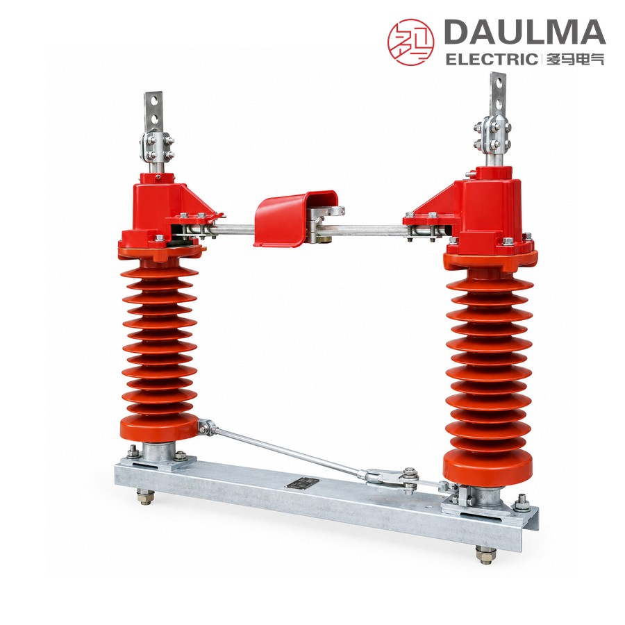
Each pole carries two support-post insulators that rotate the knife contacts through about 90°. Versions are offered without earthing, with single-side earthing, or with double-side earthing (D), and a pollution-proof type (insulator pollution grade II) is available for contaminated sites. The series meets GB 1985 and IEC 129 / IEC 694.
Model Designation
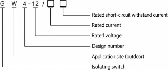
The type is designated G W 4 -12 / □ □ and decoded as follows:
- G — disconnector
- W — place of use: outdoor
- 4 — design sequence number
- 12 — rated voltage in kV
- □ — rated current in A
- □ — rated short-circuit withstand current in kA
Construction and Operation
- Double-post poles. Two support-post insulators per pole rotate in opposite directions to open or close the knife contacts, giving a wide, clearly visible break.
- Current path. Base frame, support insulators, outgoing terminals and self-cleaning finger contacts form the main conducting circuit.
- Earthing options. Supplied without earthing, with single-side earthing, or as the D type with double-side earthing; where fitted the earthing switch is interlocked against the main contacts.
- Manual operation. Driven by a manual operating mechanism through the three-phase linkage shaft; a pollution-proof insulator option is available for heavily polluted areas.
Technical Parameters
Rated Parameters
| Rated voltage (kV) | Rated current (A) | Rated peak withstand current (kA) | Rated short-time withstand current 4 s (kA) |
|---|---|---|---|
| 12 | 600 – 630 | 80 | 31.5 |
| 17.5 | 400 – 1000 | 50 | 20 |
| 40.5 | 400 – 1250 | 80 | 31.5 |
Earthing Switch (where fitted)
- Rated peak withstand current: 50 / 80 kA
- Rated short-time withstand current (4 s): 20 / 31.5 kA
- Earthing arrangements: without earthing, single-side earthing, double-side earthing (D)
Normal Service Conditions
- Altitude: 1000 to 3000 m
- Ambient temperature: not above +40℃ and not below −30℃ (−40℃ for cold areas)
- Wind pressure: not above 700 Pa (wind speed about 34 m/s)
- Seismic intensity: not above intensity 8
- Ice thickness: not above 10 mm
- Site: free from flammable or explosive hazards, chemical corrosion and violent vibration
- Insulator pollution level: general type grade 0; pollution-proof type grade II
Standards
Designed and tested to GB 1985-89 AC High-Voltage Disconnectors, IEC 129 (1984) AC Disconnectors and Earthing Switches and IEC 694 (1980) Common Specifications for HV Switchgear and Controlgear.
Installation & Wiring
Installation and Mounting
Assemble the double-post poles on the common base frame at the specified phase spacing, fix the frame to the gantry or foundation through the mounting holes, and couple the poles to the manual operating mechanism with the three-phase linkage shaft. Verify free ~90° travel, correct contact seating and the full visible break before energising, and bond the base frame to the earth grid.
Outline & Mounting Notes
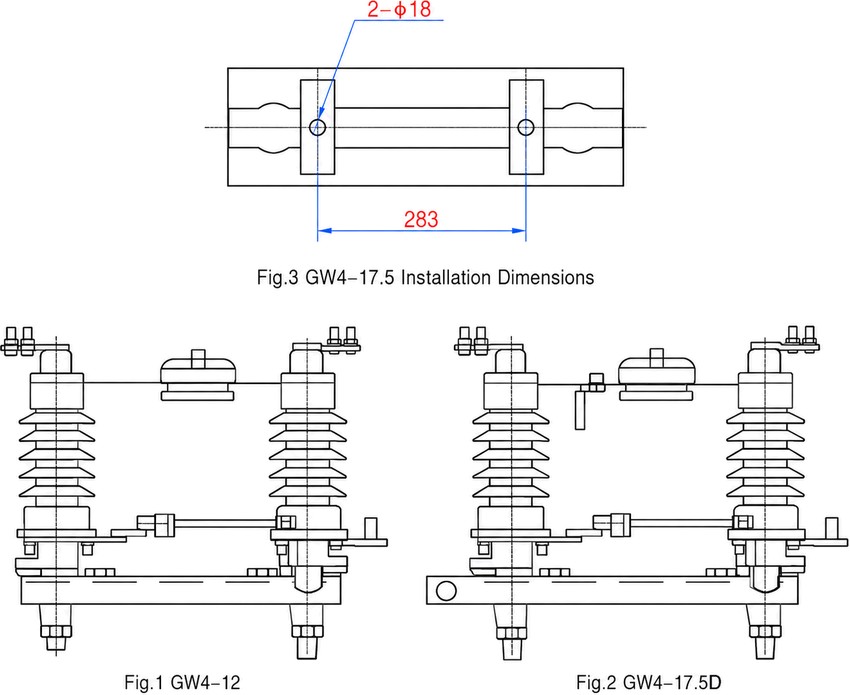
- Mounting holes: 2 × Φ18 (GW4-17.5 base), hole pitch 283 mm.
- Figure 1 GW4-12 (without earthing) and Figure 2 GW4-17.5D (with earthing) show the double-post arrangement.
Selection & FAQs
Selection Guide
- Choose the rated voltage (12 / 17.5 / 40.5 kV) and rated current to match the feeder.
- Select the earthing arrangement: without earthing, single-side earthing, or double-side earthing (D).
- For heavily polluted sites order the pollution-proof type (insulator grade II).
- Confirm the mechanism position against the gantry layout.
Frequently Asked Questions
Q1: What does the type designation GW4-12 / □□ mean?
G is the disconnector, W the outdoor place of use and 4 the design sequence number; 12 is the rated voltage in kV, and the final two fields give the rated current in A and the rated short-circuit withstand current in kA.
Q2: Can the GW4 break load or short-circuit current?
No. It only opens and closes no-load circuits under voltage and provides a visible isolating gap; load and fault currents are cleared by the associated circuit breaker.
Q3: What earthing versions are available?
Without earthing, single-side earthing, and double-side earthing (D); the earthing switch is interlocked against the main contacts to prevent misoperation.
Q4: What are the main rated values?
Rated voltage 12 / 17.5 / 40.5 kV; rated current 600–630 / 400–1000 / 400–1250 A; peak withstand 80 / 50 / 80 kA; short-time withstand (4 s) 31.5 / 20 / 31.5 kA.
Q5: What are the service conditions?
Altitude 1000–3000 m, ambient −30℃ (−40℃ cold areas) to +40℃, wind pressure up to 700 Pa (about 34 m/s), seismic intensity up to 8, and ice thickness up to 10 mm.
Q6: Which standards does it comply with?
GB 1985-89, IEC 129 (1984) and IEC 694 (1980). See the disconnector range for related models.