

Overview
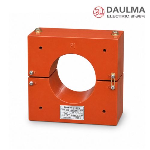
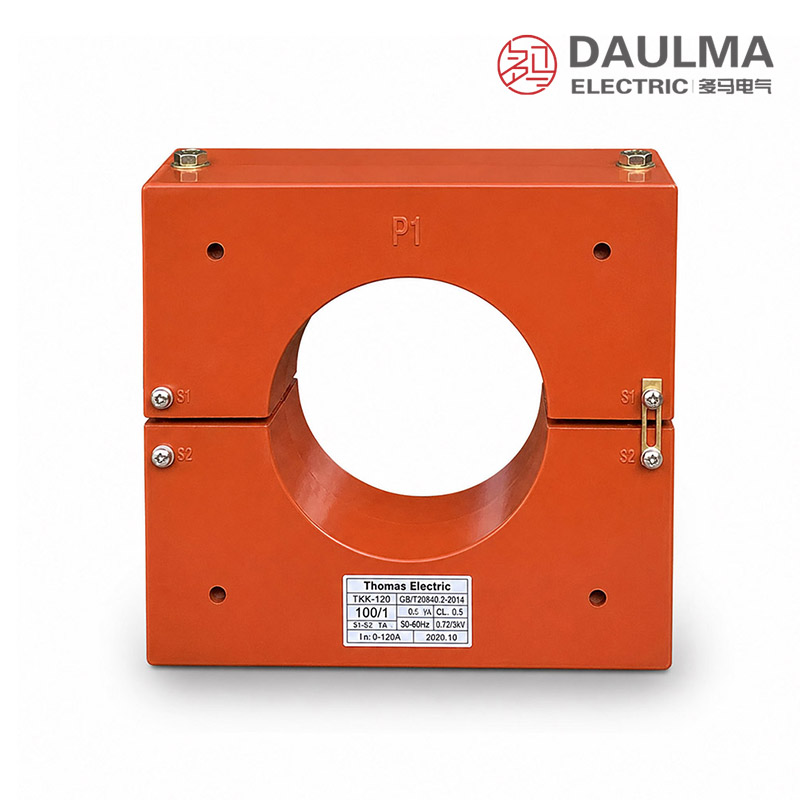
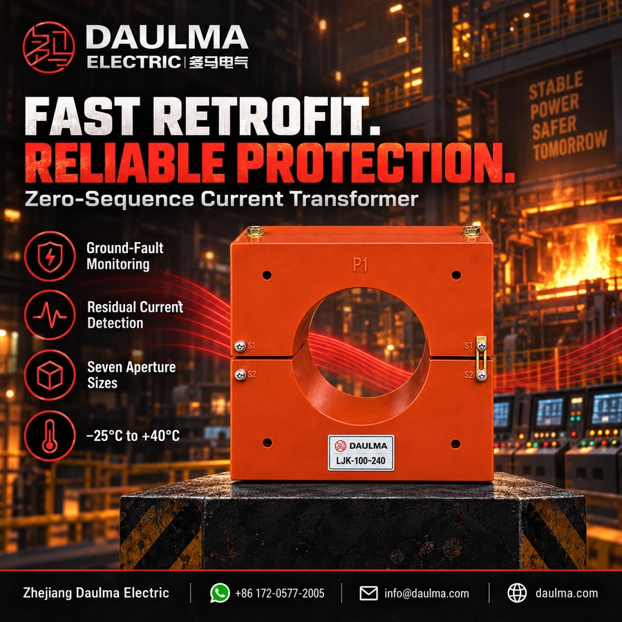
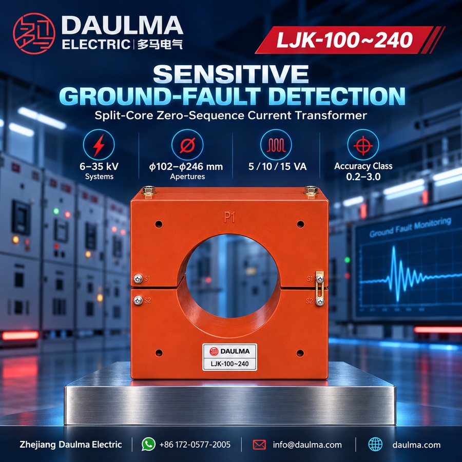
The LJK-phi100~phi240 series zero-sequence current transformers are high-precision electromagnetic devices engineered for ground fault detection, residual current monitoring, and earth leakage protection in low and medium-voltage AC power distribution systems. By leveraging electromagnetic induction, these transformers accurately sense unbalanced (zero-sequence) currents in three-phase circuits and deliver isolated secondary signals for relay tripping, fault location, and system diagnostics.
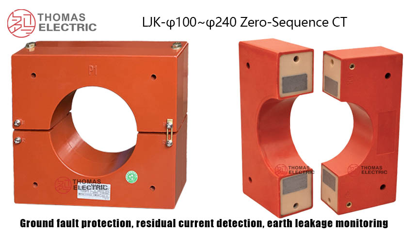
Built with a split-core design and sealed epoxy resin core, the LJK series enables quick retrofit installation without disconnecting primary conductors, making it ideal for both new installations and upgrades in indoor industrial and utility environments.
Key Ratings Snapshot
| Parameter | Value |
|---|---|
| Voltage range | 6kV : 35 kV |
| Frequency | 50 Hz : 60 Hz |
| Aperture diameter | phi100 mm : phi240 mm |
| Accuracy classes | 0.2, 0.5, 1.0, 3.0 |
| Rated burden | 5 VA, 10 VA, 15 VA |
| Secondary terminals | K1, K2 |
| Installation type | Split-core (openable) |
| Enclosure material | ABS plastic + epoxy resin sealed core |
| Protection rating | IP54 (indoor) |
| Primary application | Ground fault & residual current protection |
Model Designation
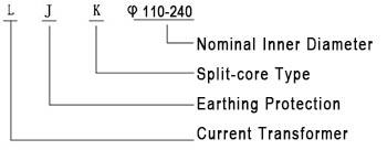
- L : Current transformer (CT)
- J : Ground (earth) protection application
- K : Split-core (openable/split-type) structure
- phi100~phi240 : Inner aperture diameter (mm)
Construction
The LJK series features a ring-type magnetic core fully encapsulated in epoxy resin, housed within a robust ABS engineering plastic enclosure. This construction ensures excellent insulation integrity, moisture resistance, and long-term stability against corrosion and thermal stress in demanding indoor environments. The high-permeability core enables sensitive detection of even small zero-sequence currents, critical for reliable ground fault protection.
Its split-core (openable) configuration allows installation around live or de-energized cable bundles without disconnection, significantly reducing downtime during retrofits. Precision-machined mating surfaces and anti-rust treatment maintain magnetic circuit continuity and mechanical reliability over the product’s service life.
Technical Parameters
Service Conditions
- Installation environment: Indoor only
- Altitude: <= 2000 m (higher requires specification)
- Ambient temperature: -25 degC to +40 degC
- Relative humidity: <= 95% (no condensation)
- Environmental conditions: Free from conductive dust, corrosive gases, severe vibration, or mechanical shock
Technical Data
| Model | Aperture D(Ï) mm |
Outer Width A mm |
Height C mm |
Mounting Hole d(Ï) mm |
|---|---|---|---|---|
| LJK-100 | 102 | 214 | 141 | 9 |
| LJK-120 | 120 | 232 | 160 | 9 |
| LJK-140 | 145 | 275 | 178 | 9 |
| LJK-160 | 165 | 293 | 195 | 9 |
| LJK-180 | 187 | 317 | 255 | 9 |
| LJK-200 | 206 | 370 | 285 | 9 |
| LJK-240 | 246 | 410 | 315 | 10.5 |
Installation & Wiring
Installation Diagram
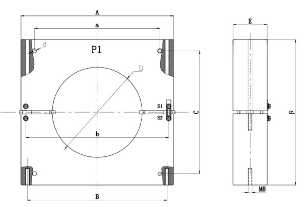
The LJK series split-core zero-sequence current transformers are designed for straightforward installation on existing cable systems. The unit separates into two halves, allowing placement around energized or de-energized conductors without interruption. Proper alignment and secure fastening are essential to maintain magnetic circuit integrity and measurement accuracy.
Outline Dimensions
| Model | A mm | B mm | C mm | E mm | F mm | a mm | b mm | D(Ï) mm | d(Ï) mm |
|---|---|---|---|---|---|---|---|---|---|
| LJK-100 | 214 | 190 | 141 | 50 | 188 | 152 | 184 | 102 | 9 |
| LJK-120 | 232 | 208 | 160 | 50 | 206 | 170 | 202 | 120 | 9 |
| LJK-140 | 275 | 255 | 178 | 71 | 245 | 200 | 255 | 145 | 9 |
| LJK-160 | 293 | 267 | 195 | 71 | 262 | 220 | 271 | 165 | 9 |
| LJK-180 | 317 | 290 | 255 | 71 | 302 | 260 | 297 | 187 | 9 |
| LJK-200 | 370 | 348 | 285 | 85 | 330 | 310 | 340 | 206 | 9 |
| LJK-240 | 410 | 383 | 315 | 79 | 383 | 336 | 390 | 246 | 10.5 |
Selection & FAQs
Selection Guide
- Measure the maximum diameter of the complete cable bundle and select LJK-100, 120, 140, 160, 180, 200 or 240 with adequate clearance for insulation and installation tolerances.
- Define the required function—earth-fault tripping, residual-current monitoring or diagnostics—and select accuracy class 0.2, 0.5, 1.0 or 3.0 accordingly.
- Add the connected relay or instrument burden to the calculated secondary-lead burden, then choose 5VA, 10VA or 15VA without exceeding the rated output.
- Confirm the required secondary signal, relay pickup range and project-specific ratio with the manufacturer because ratio data is not fixed by the aperture designation.
- Check indoor environmental limits, cabinet dimensions, mounting-hole layout, conductor and screen routing, and safe access for precise split-face alignment.
Frequently Asked Questions
Q1: What does the LJK-100~240 measure?
It senses the vector sum of currents in all conductors passing through its aperture. A non-zero result indicates residual or earth-fault current for relay tripping, monitoring or fault diagnosis.
Q2: Does LJK-100 mean a 100A current ratio?
No. The number identifies aperture size: LJK-100 has an actual opening of about 102mm. The current ratio and secondary specification must be confirmed separately for the protection scheme.
Q3: Which aperture sizes are available?
Actual openings are approximately 102, 120, 145, 165, 187, 206 and 246mm. Select from measured cable-bundle dimensions plus insulation and installation clearance.
Q4: Can it be retrofitted without disconnecting the primary cables?
Yes. The housing and magnetic core separate into matched halves for installation around an existing bundle. The circuit should be made safe and installation performed by qualified personnel under the approved procedure.
Q5: Which accuracy class and burden should be selected?
Choose class 0.2 or 0.5 for higher-precision monitoring where specified, or class 1.0 or 3.0 where the protection design permits. The selected 5VA, 10VA or 15VA output must cover both device and lead burden.
Q6: Why must upper and lower core halves remain paired?
Each pair is matched to maintain a continuous magnetic circuit. Mixing halves or leaving a gap changes the magnetic characteristics and can materially reduce sensitivity and accuracy.
Q7: Which conductors pass through the aperture?
All phase conductors of the protected circuit pass through together in the same direction. Neutral, screen, armour and PE conductors must be routed exactly as defined by the grounding and residual-current scheme.