Overview
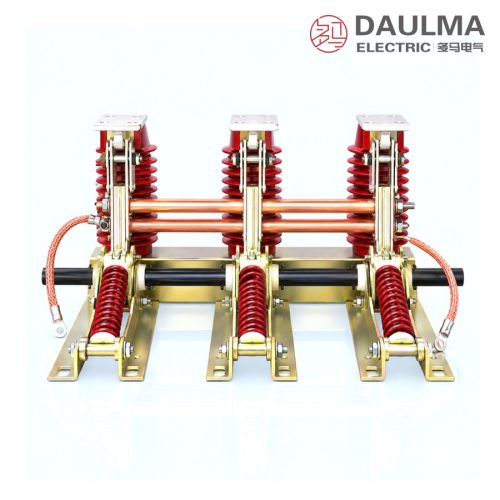
The JN17-12/40 is a combined indoor high voltage earthing switch for 3–10 kV (rated voltage 12 kV), 50/60 Hz three-phase power systems. It has a certain short-circuit making capacity that protects the other electrical equipment inside the switchgear from damage, matches various types of high voltage switchgear, and provides the protective earth for high voltage equipment during inspection and maintenance. The combined arrangement can be supplied together with a live-voltage indicating device.
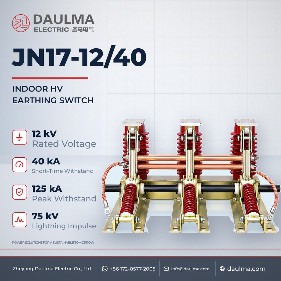
It is rated 40 kA rated short-time withstand current and is offered with phase-center (between-pole) distances of 210, 220, 230, 250 and 275 mm to suit different cubicles; the suffix G denotes the high-altitude type. Remaining ratings such as short-circuit duration, peak withstand and making current and insulation level follow the nameplate / technical agreement.
Model Designation
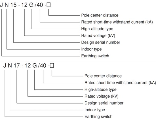
The type is designated JN 17 – 12 G / 40 – □ and decoded as follows:
- J — earthing switch
- N — indoor device
- 17 — design number (also built as the JN15-12G/40 variant)
- 12 — rated voltage in kV
- G — high-altitude type
- 40 — rated short-time withstand current in kA
- □ — phase-center (between-pole) distance in mm
Construction and Operation
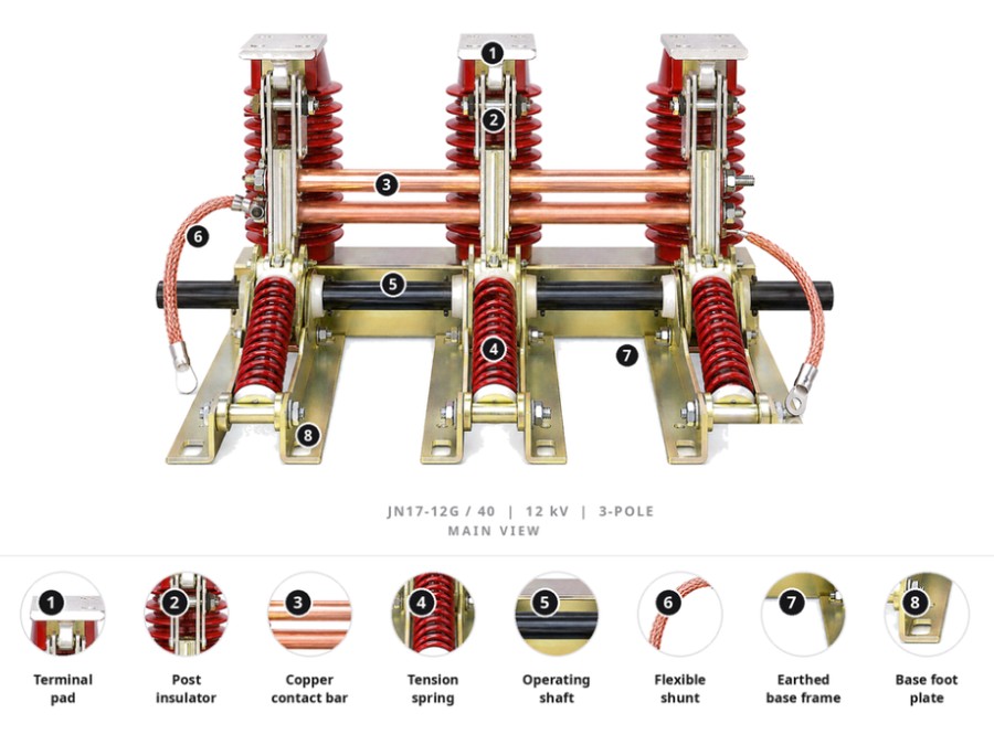
The JN17-12/40 uses a combined three-pole arrangement in which the earth knives are mounted on support insulators above a common frame and are coupled through a transmission shaft to the operating mechanism so that all three poles make or break the earth connection together. The knives engage static contacts sized to close reliably onto a short-circuit current, and the mechanism can be interlocked with the associated switchgear or cubicle door to prevent mal-operation. As a combined type it can be furnished with a live-voltage indicating device to show the energised state of the busbar, and the frame is bonded to the earth network to complete the protective path.
Technical Parameters
Rated Parameters
| Item | Unit | Data |
|---|---|---|
| Rated voltage | kV | 12 (applicable to 3–10 kV systems) |
| Rated frequency | Hz | 50 / 60 |
| Rated short-time withstand current | kA | 40 |
| Phase-center (between-pole) distance | mm | 210 / 220 / 230 / 250 / 275 |
| High-altitude type | — | G suffix |
Operating Conditions
- Altitude: not above 1000 m
- Ambient temperature: upper limit +40℃, lower limit −10℃
- Seismic: intensity not above 8 degrees
- Site: free from flammable or explosive hazard, severe dust, chemical corrosion and violent vibration
Installation & Wiring
Installation and Mounting
Fix the earthing-switch frame to the cubicle mounting plane at the selected phase-center distance, keeping the earth knives and static contacts clear of obstructions. Couple the three poles to the operating mechanism through the transmission shaft, connect the flexible earth conductor (standard length L = 240 mm unless otherwise agreed), then verify simultaneous and full contact seating of all three poles, correct interlock action and bonding of the frame to the earth network before energising.
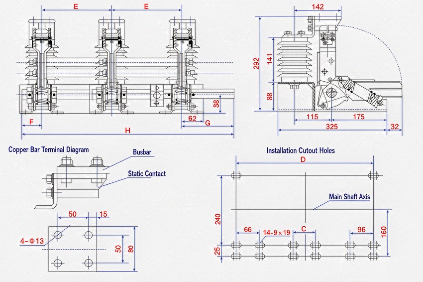
Outline & Mounting Dimensions
| Model | E (mm) | F (mm) | G (mm) | H (mm) | D (mm) |
|---|---|---|---|---|---|
| JN17-12/40-210 | 210 | 50 | 185 | 655 | 516 |
| JN17-12/40-220 | 220 | 50 | 185 | 675 | 536 |
| JN17-12/40-230 | 230 | 50 | 185 | 695 | 556 |
| JN17-12/40-250 | 250 | 50 | 185 | 735 | 596 |
| JN17-12/40-275 | 275 | 50 | 210 | 810 | 646 |
E is the phase-center (between-pole) distance; dimensions in mm.
Selection & FAQs
Ordering Information
- When ordering, state the product model, the phase-center distance, and whether a live-voltage indicating device is required (and its type).
- State whether the flexible earth connection needs to be lengthened (standard length L = 240 mm).
- Any special requirement is to be settled between the user and the manufacturer.
Frequently Asked Questions
Q1: What does the type designation JN17-12G/40 mean?
J is the earthing switch and N the indoor device; 17 is the design number, 12 the rated voltage in kV, G the high-altitude type, 40 the rated short-time withstand current in kA, and the trailing figure the phase-center (between-pole) distance in mm.
Q2: What is the JN17-12/40 used for?
It is a combined indoor high voltage earthing switch for 3–10 kV, 50/60 Hz systems, matched with various high voltage switchgear to provide protective earthing during equipment inspection and maintenance, with a certain short-circuit making capacity to protect other equipment in the cubicle.
Q3: What is the rated short-time withstand current?
40 kA. Other ratings such as short-circuit duration, peak withstand current, making current and insulation level follow the nameplate / technical agreement.
Q4: What does the “combined” type mean?
The earthing switch can be supplied as a combined arrangement together with a live-voltage indicating device that shows the energised state of the busbar.
Q5: What phase-center distances are available?
Five types — 210, 220, 230, 250 and 275 mm, with overall dimension H of 655, 675, 695, 735 and 810 mm respectively.
Q6: Where can I see related products?
See the high voltage earthing switches range for related models.