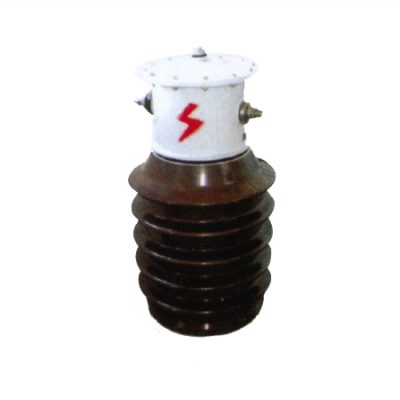
LCWD1-35, LABN1-35W2 Compact Oil-Insulated Outdoor Current Transformer
LCWD1-35 Current Transformer Overview The LCWD1-35 (LABN1-35W2) current transformer is an oil-insulated, outdoor device, engineered for use in 35kV, and below AC power systems with rated frequencies of 50Hz or 60Hz. Oil-Insulated Outdoor Current Transformer is Designed for energy metering, current measurement, and relay protection, it combines compact design, lightweight construction, and exceptional reliability. Its […]
LCWD1-35 Current Transformer Overview
The LCWD1-35 (LABN1-35W2) current transformer is an oil-insulated, outdoor device, engineered for use in 35kV, and below AC power systems with rated frequencies of 50Hz or 60Hz. Oil-Insulated Outdoor Current Transformer is Designed for energy metering, current measurement, and relay protection, it combines compact design, lightweight construction, and exceptional reliability. Its robust vacuum-dried and oil-filled structure ensures excellent insulation and long-term durability, making it ideal for medium-voltage power systems operating in challenging outdoor environments.
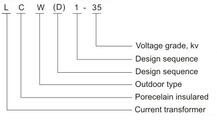
Type Designation for LCWD1-35 CT
Key Features of LCWD1-35 (LABN1-35W2) Current Transformers
- L: Current transformer.
- C: Porcelain insulated.
- W: Outdoor type.
- D: Design sequence with protection class.
- 1: Design sequence.
- 35: Voltage grade for 35kV systems.
LCWD1-35 (LABN1-35W2) current transformers are robustly designed for outdoor use, featuring durable porcelain insulation and a customizable oil-immersed tank. They provide reliable performance in medium-voltage systems with specific adjustments available for dimensions, materials, and applications.
Service Conditions for LCWD1-35 Current Transformers
- Installation Location: Suitable for outdoor environments.
- Ambient Temperature:
- Maximum: +40°C
- Minimum: -25°C
- Altitude: Up to 1000 meters above sea level.
- Pollution Class: Available in Class II and Class III for enhanced resistance to environmental factors.
- Customization Options: Oil-immersed tanks can be tailored to meet specific service conditions, including unique dimensions, materials, and designs.
The LCWD1-35 current transformer is designed to deliver reliable performance in demanding outdoor environments, meeting a wide range of application needs. Its compact and durable design ensures long-lasting functionality, while the external metal casing can be fully customized to suit specific requirements, including dimensions, materials, and finishes, providing a tailored solution for diverse applications.
Construction of LCWD1-35 CT
The LCWD1-35 current transformer features a compact structure, small volume, and lightweight design. The transformer body undergoes vacuum drying treatment and is housed in a bushing filled with transformer oil to ensure optimal insulation and durability.
- Primary and Secondary Windings: The upper half of the bushing contains the primary winding, while the lower half contains the secondary winding.
- Mounting: The bushing is securely fixed to the pedestal for stability.
- Oil Storage Cabinet: Positioned at the top of the bushing, the oil storage cabinet is equipped with dials that display different temperatures and oil levels for monitoring and maintenance.
- Terminal Configuration:
- The primary winding’s starting terminal (P1) is insulated from the cabinet wall using small porcelain bushings.
- The terminal marked P2 is directly connected to the cabinet wall for efficient electrical connection.
Technical Data for LCWD1 35KV Current Transformer
- Rated Insulation Level: 40.5/95/185kV.
- Rated Secondary Current: 5A.
- Rated Primary Current and Accuracy Classes: See specifications table.
- Creepage Distance: ≥735mm (General), ≥1100mm (W2).
- Parameter Selection: Please refer to the technical table.
Custom adjustments available upon request.
| Rated Primary
Current (A) |
Accuracy Classed
Combination |
Related Output (VA) | Short-time
Thermal Current (KA/S) |
Rated Dynamic
Current (I dyn) (KA) |
||
|---|---|---|---|---|---|---|
| 0.2S | 0.5 | 10P20 | ||||
| 5 | 0.5/10P15 0.5/10P15 0.2/0.5 0.2/0.2 |
30 | 50 | 50 | 0.375 | 0.95 |
| 10 | 0.75 | 1.9 | ||||
| 15 | 1.12 | 2.9 | ||||
| 20 | 1.5 | 3.8 | ||||
| 30 | 2.25 | 5.7 | ||||
| 40 | 3 | 7.6 | ||||
| 50 | 3.75 | 9.6 | ||||
| 75 | 5.62 | 14.5 | ||||
| 100 | 7.5 | 19.2 | ||||
| 200 | 11.25 | 28.7 | ||||
| 300 | 15 | 38.3 | ||||
| 400 | 22.5 | 57.5 | ||||
| 600 | 30 | 76.5 | ||||
| 800 | 45 | 115 | ||||
| 1000 | 45 | 115 | ||||
| 1200 | 45 | 115 | ||||
| 1500 | 45 | 115 | ||||
Accuracy limit ractor of class 10P
Installation Dimensions
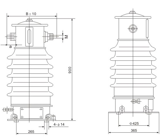
LCWD1-35, LABN1-35W2 Compact Oil-Insulated CT Installation Dimensions
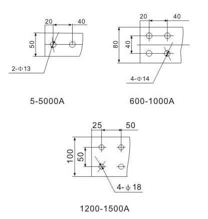
Spiral Rod Connection
| Rated Primary
Current (A) |
M |
| 5-500 | M22 × 1.5 |
| 600-1000 | M27 × 1.5 |
| 1200-1500 | M30 × 1.5 |
Copper Bar Type Connection
| Rated Primary Current (A) > | B |
| 5-500 | 410 |
| 600-1000 | 440 |
| 1200-1500 | 440 |
Ordering Guidelines and Special Requirements
- Type and Current Ratio: Specify transformer type and desired primary current rating.
- Accuracy Class and Output: Indicate required accuracy class and secondary output specifications.
- Insulation Level: Confirm insulation level and pollution class.
- Customization: Provide details for custom dimensions, materials, design adjustments, or tailored oil tank and transformer casing.
- Installation Requirements: Include ambient conditions and installation location.
Contact our team for tailored solutions, including customizable transformer casings and oil tanks.
- Analysis of the Impact of Current Transformer Faults on Energy Meter Accuracy
- Introduction to Combined Transformers and Their Classification
- Magnetic Saturation in 20kV Voltage Transformers and Its Adverse Effects
- Analysis of the Impact of Incorrect CT S1 and S2 Connections and Reversed Input Lines
- Single-Phase Voltage Transformers Role, Function, and Importance in Power Systems
- 3 Voltage Transformer Faults and Solutions: Ensuring Accurate Measurement and Protection
