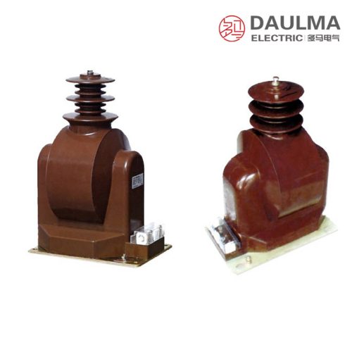
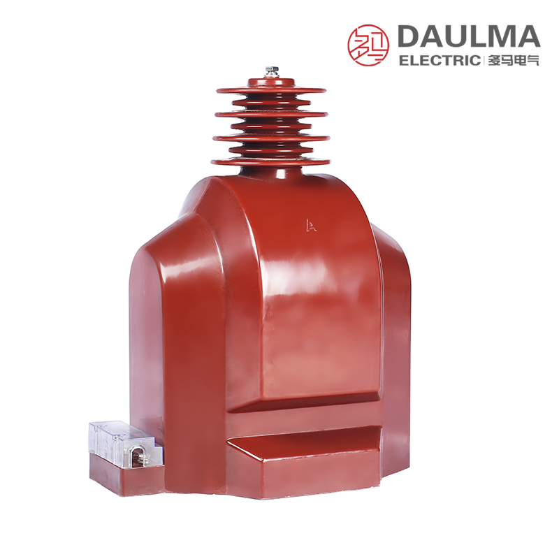
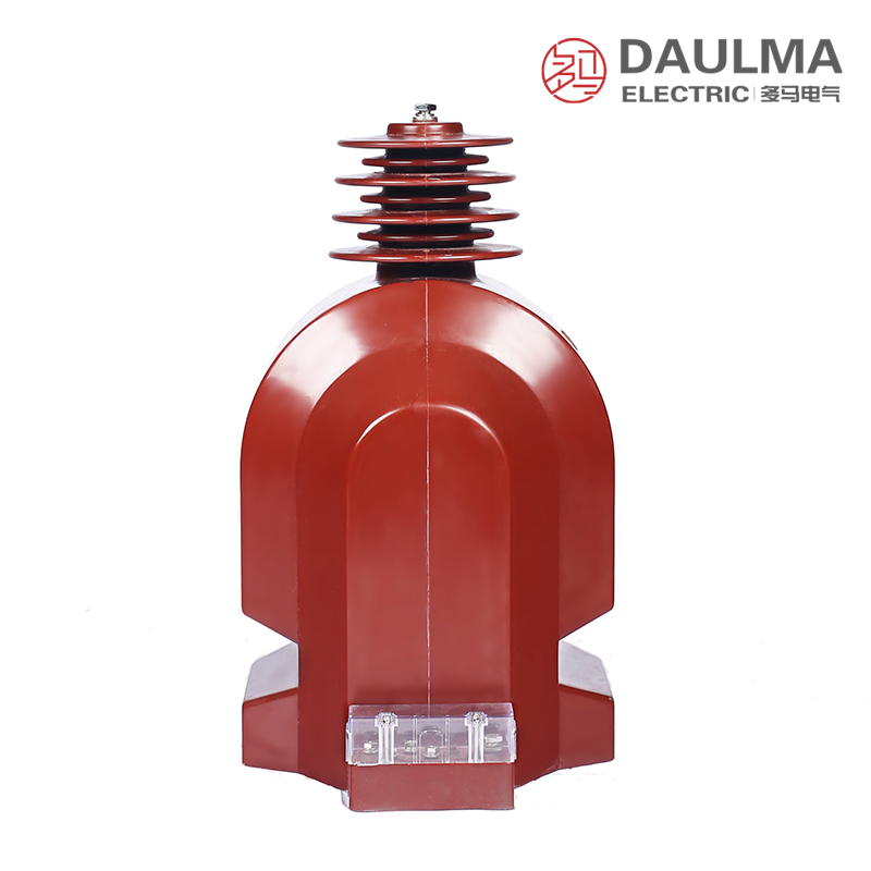
Overview
The JDZX9-35 outdoor cast-resin voltage transformer is a precision electromagnetic instrument engineered for accurate voltage measurement, energy metering, and relay protection in 35 kV AC outdoor power systems. It operates on electromagnetic induction principles to deliver galvanically isolated secondary voltage signals proportional to the primary system voltage.
Built with fully enclosed epoxy resin insulation, this transformer ensures long-term reliability under harsh outdoor conditions, including UV exposure, moisture, and pollution. Its robust design supports stable performance in medium-voltage distribution networks while meeting stringent international and national standards.
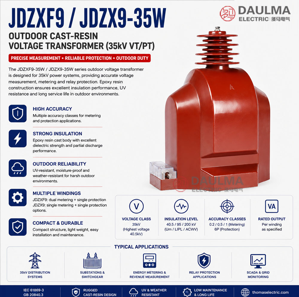
Key Ratings Snapshot
| Item | Specification |
|---|---|
| System voltage class | 35 kV (outdoor) |
| Rated frequency | 50 Hz (60 Hz available) |
| Rated voltage ratio | 35000/â3 / 100/â3 / 100/3 V |
| Accuracy classes | 0.2 / 6P or 0.5 / 6P |
| Rated burden | 30 / 100 VA or 50 / 100 VA per winding |
| Burden power factor | cosÏ = 0.8 (inductive) |
| Insulation level | 40.5 / 95 / 200 kV (Um/LIPL/ACWV) |
| Pollution grade | Grade II (Grade IV available) |
| Construction type | Outdoor cast-resin, support-type |
| Applicable standards | IEC 61869-3; GB 20840.3-2013 |
Model Designation
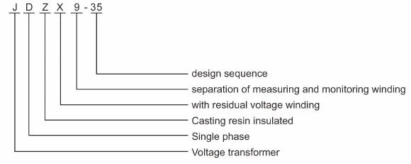
- J: Voltage transformer (VT / PT)
- D: Single-phase
- Z: Cast-resin (epoxy) insulated, fully enclosed structure
- X: Outdoor (weatherproof) design
- 9: Design code (platform/iteration)
- 35: Voltage class (kV)
- W: Outdoor pollution grade variant (extended creepage)
Construction
The JDZX9-35 features a support-type post structure designed for secure mounting in outdoor substations. Its core is made of high-quality silicon steel laminations to minimize no-load losses, while the entire assembly is encapsulated in UV-resistant epoxy resin. This fully enclosed construction provides excellent resistance to moisture, contamination, thermal cycling, and aging.
The integrated primary and secondary insulation system incorporates extended creepage distances to meet Grade II (standard) or Grade IV (severe pollution) requirements. The design ensures reliable electrical clearance and mechanical strength for long-term operation in demanding environments up to 40 deg C ambient temperature and 1000 m altitude.
Technical Parameters
Service Conditions
- Installation environment: Outdoor installation
- Altitude: <= 1000 m above sea level
- Ambient temperature: -25 deg C to +40 deg C
- Daily average temperature: <= 30 deg C
- Pollution grade: Grade II standard (Grade IV available)
- Environmental conditions: Resistant to UV, moisture; no severe corrosive gases or explosive media
Technical Data
| Model | Rated Voltage Ratio (V) |
Accuracy Class Combination |
Rated Output (VA) |
Maximum Output (VA) |
Rated Insulation Level (kV) |
|---|---|---|---|---|---|
| JDZX9-35 | 35000/â3 / 100/â3 / 100/3 | 0.2 / 6P | 30 / 100 | 600 | 40.5 / 95 / 200 |
| JDZX9-35 | 35000/â3 / 100/â3 / 100/3 | 0.5 / 6P | 50 / 100 | 600 | 40.5 / 95 / 200 |
Selection Note: Voltage ratios are expressed as phase-to-ground values. Only one secondary tap shall be used at a time. Custom accuracy or burden combinations available upon request with technical confirmation.
Frequently Asked Questions
Q1: Can this 35kV voltage transformer be installed at high altitudes?
It is designed for altitudes up to 1000 meters above sea level. For higher elevation projects, please contact us for derating details.
Q2: Which secondary accuracy class is suitable for protective relaying?
The 6P accuracy class is intended for protection circuits. The 0.2 or 0.5 classes are designated for measurement and metering applications.
Q3: How many secondary taps can be used simultaneously on this transformer?
Only one secondary tap shall be used at a time to ensure proper operation. Voltage ratios are expressed as phase-to-ground values.
Q4: Is this cast resin transformer suitable for severe outdoor pollution?
It meets the Grade II pollution standard by default. Grade IV pollution resistance is available upon specific project requirements and technical confirmation.
Q5: Can we request custom accuracy or burden combinations for this model?
Yes, custom accuracy and burden combinations are available upon request. Please submit your specific technical parameters for factory confirmation.
Q6: What standard routine tests are performed before shipment?
Standard factory testing details and specific certification documents are subject to confirmation. Please contact our sales team for the exact test reports.
Q7: What is the primary application of the JDZX9-35 voltage transformer?
It is used for voltage measurement, monitoring, and protective relaying in 35kV outdoor power distribution systems. It features UV and moisture-resistant cast resin insulation.
Installation & Wiring
Installation Diagram
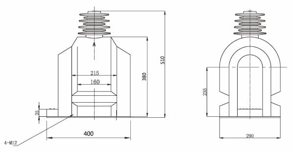
The JDZX9-35 must be securely mounted on a stable outdoor foundation using the designated fixing holes. Primary connection is made via overhead line terminal or busbar connector, while secondary circuits must be properly wired and grounded per safety standards.
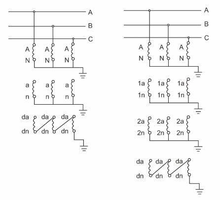
Outline Dimensions
| Dimension | Value (mm) |
|---|---|
| Total height | Approx. 720 |
| Base width | Approx. 220 |
| Mounting hole pattern | phi14 x 4 holes, 180 mm pitch |
| Primary terminal height | Approx. 680 |
| Secondary terminal box | IP54 rated, bottom-mounted |
Safety Notice: Secondary circuits must maintain at least one grounded point per winding for personnel safety. Before maintenance, disconnect and safely ground all primary circuits in accordance with local electrical safety regulations. Always verify de-energization before approaching equipment.
Selection & FAQs
Frequently Asked Questions
Q1: How do I select the appropriate accuracy class combination (e.g., 0.2/6P vs. 0.5/6P) for the JDZX9-35 voltage transformer in a 35 kV outdoor substation?
The choice between 0.2/6P and 0.5/6P depends on your application’s dual requirements for metering precision and protection reliability. The first class (0.2 or 0.5) governs metering accuracy under normal load conditions per IEC 61869-3: at rated burden, a 0.2-class VT must maintain error within ±0.2% in ratio and ±10′ in phase angle, suitable for revenue-grade energy metering. The second class (6P) applies to the protection winding and allows ±6% composite error at 5× rated voltage—adequate for overvoltage and ground-fault relaying. If your utility requires Class 0.2 for billing compliance (e.g., per GB/T 17215), choose 0.2/6P; otherwise, 0.5/6P offers cost-effective performance for non-revenue metering with identical protection capability.
Q2: What are the critical installation precautions to avoid performance degradation or safety hazards when mounting the JDZX9-35 outdoors?
Three key precautions must be observed: (1) Ensure the foundation is level and rigid—misalignment exceeding 2° can induce mechanical stress on the epoxy resin housing, risking microcracks during thermal cycling. (2) Ground the secondary circuit at exactly one point per winding (typically at the terminal box) to prevent circulating currents while maintaining personnel safety; multiple grounds create ground loops that distort measurement signals. (3) Verify creepage distance adequacy: standard Grade II units (JDZX9-35) provide ~25 mm/kV; for coastal or industrial sites with conductive pollution, specify the “W” variant (Grade IV) with extended sheds offering ≥31 mm/kV. Also, confirm ambient temperature stays within –25°C to +40°C and altitude ≤1000 m—higher altitudes require derating or custom insulation coordination.
Q3: How does the rated burden (e.g., 30/100 VA vs. 50/100 VA) impact real-world performance, and how should I calculate total connected burden?
Rated burden defines the maximum VA load each secondary winding can drive while maintaining specified accuracy. For the JDZX9-35, the metering winding is typically rated 30 VA (for 0.2 class) or 50 VA (for 0.5 class), while the protection winding is 100 VA. Total connected burden includes all downstream devices plus wiring losses: e.g., a digital meter (5 VA) + SCADA RTU (8 VA) + 50 m of 2.5 mm² Cu cable (resistance ≈0.35 Ω → I²R loss ≈2 VA at 5 A secondary current) totals ~15 VA—well within 30 VA. Exceeding rated burden increases ratio/phase errors nonlinearly; operating below 25% of rated burden may also degrade accuracy due to core magnetization effects. Always sum VA demands at cosφ = 0.8 (inductive), as specified.
Q4: Why does the JDZX9-35 include an auxiliary winding (100/3 V), and how should it be used in ground-fault detection schemes?
The auxiliary (tertiary) winding provides a residual voltage output (100/3 V phase-to-neutral) proportional to zero-sequence voltage during ground faults in effectively grounded 35 kV systems. In a three-phase installation, connecting all three auxiliary windings in open-delta configuration yields 100 V across the open terminals during a single-line-to-ground fault—triggering 59N or 27TN relays. This winding is isolated from metering/protection circuits to avoid loading effects and is rated 100 VA at 6P accuracy. Note: Only one secondary (metering, protection, or auxiliary) should be loaded at a time unless explicitly validated by the manufacturer, as mutual coupling can alter error characteristics.
Q5: How does the cast-resin construction of the JDZX9-35 compare to oil-filled or SF6-insulated outdoor VTs in terms of lifecycle reliability and maintenance?
Cast-resin VTs like the JDZX9-35 eliminate fire risk, oil leakage, and gas handling associated with oil/SF6 alternatives. Epoxy resin provides superior tracking resistance (CTI >600) and UV stability, yielding >30-year service life with zero maintenance—no oil sampling, gas pressure checks, or bushing cleaning required. However, they exhibit lower thermal mass than oil-filled units, limiting short-time overload capacity (max output = 600 VA vs. continuous 100 VA). In polluted environments, cast-resin’s hydrophobic surface resists contamination buildup better than porcelain, but requires proper shed profile design (hence Grade IV option). For 35 kV outdoor applications prioritizing safety, minimal upkeep, and compact footprint, cast-resin is often preferred over legacy technologies.
Q6: What customization options are available for the JDZX9-35 to meet specific project requirements, and what lead-time implications should procurement teams anticipate?
Key customizable parameters include: (1) Accuracy/burden combinations beyond standard 0.2/6P (30/100 VA) or 0.5/6P (50/100 VA)—e.g., 0.2S/3P for smart-grid metering; (2) Pollution grade upgrade to Grade IV (suffix “W”) with increased creepage distance; (3) Frequency adaptation (60 Hz instead of default 50 Hz); (4) Secondary terminal configurations (e.g., MCB-integrated boxes). Custom orders typically add 4–6 weeks to standard lead times (usually 8–10 weeks) due to dielectric testing revalidation per IEC 61869-3. Procurement teams should confirm customization needs during RFQ stage—late changes may void type-test certificates or require new insulation coordination studies.
Q7: How should engineers interpret the insulation level “40.5/95/200 kV” for system coordination in a 35 kV network?
This notation follows IEC 60071: Um = 40.5 kV (highest system voltage), LIPL = 95 kV (lightning impulse withstand), ACWV = 200 kV (power frequency withstand for 1 min). For a 35 kV system (nominal), Um = 40.5 kV ensures compatibility with standard BIL coordination. The 95 kV LIPL must exceed the protective level of connected surge arresters (typically 85–90 kV for 35 kV class), providing adequate margin. The 200 kV ACWV validates insulation integrity against switching surges and temporary overvoltages. Engineers must verify that these levels align with substation insulation coordination studies—mismatched levels risk flashover during transient events or unnecessary overdesign.
Q8: What are common troubleshooting steps if the JDZX9-35 exhibits abnormal secondary voltage readings or overheating during operation?
First, confirm secondary circuits are not open-circuited—a VT secondary must never operate unloaded, as this causes core saturation and excessive voltage spikes. Use a multimeter to verify burden continuity. Second, measure actual burden: excessive VA draw (e.g., from faulty meters or long cables) can cause thermal rise and ratio drift. Third, inspect for external contamination—salt or dust deposits on the resin surface in humid conditions may create leakage paths, detectable via IR thermography showing localized heating. Fourth, validate grounding: floating secondary grounds induce capacitive coupling errors. If issues persist, perform excitation test per IEEE C57.13: apply 100–120% of rated secondary voltage to the metering winding and check no-load current—values >30% of nameplate indicate core degradation. Always de-energize and ground primary before physical inspection.