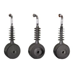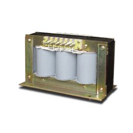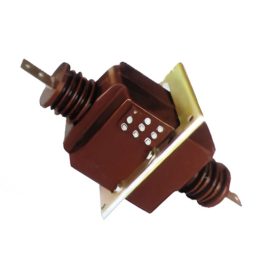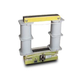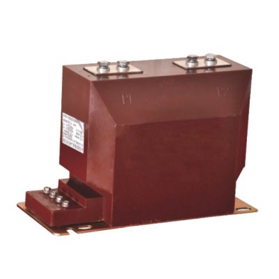
LZZBJ12-10 Epoxy Insulated Indoor Current Transformer
LZZBJ12-10 Epoxy Insulated Indoor Current Transformer, is a 10KV High-Voltage Current Transformer, It is suitable for metering and protective relaying in indoor power systems, with a rated voltage of 10KV or below and a frequency range of 50–60Hz. It features a pillar-type structure, fully encapsulated with epoxy resin, offering high accuracy, low partial discharge, compact […]
LZZBJ12-10 Epoxy Insulated Indoor Current Transformer, is a 10KV High-Voltage Current Transformer, It is suitable for metering and protective relaying in indoor power systems, with a rated voltage of 10KV or below and a frequency range of 50–60Hz. It features a pillar-type structure, fully encapsulated with epoxy resin, offering high accuracy, low partial discharge, compact size, lightweight, and strong thermal and dynamic stability. It is resistant to humidity and pollution, operates reliably under various conditions, and requires no maintenance.
LZZBJ12-10 Current Transformer Type designation
The current transformer is available in three variants: LZZBJ12-10 A, LZZBJ12-10 B, and LZZBJ12-10 C.
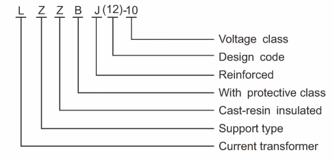
The Key Features and Structure of LZZBJ12-10 Current Transformer:
- L: Represents the “Current Transformer” type.
- Z: Support type.
- Z: Cast-resin insulated
- B: Refers to the “With protective class”.
- J: Refers to the “Reinforced” design for enhanced mechanical strength.
- (12): Design code.
- 10: Denotes the voltage class
This model designation explains the LZZBJ12-10 current transformer, highlighting its reinforced, cast-resin insulated design, protection class, and suitability for different voltage classes in power systems.
LZZBJ12-10 Current Transformer Service conditon
- Altitude: ≤1000m
- Ambient Temperature: -5°C to +40°C
- Relative Humidity: ≤90% at 20°C
- Environment: Free from harmful gases, chemicals, or pollutants that could damage insulation.
- Vibration: Stable, without chattering or impact.
LZZBJ12-10 CT Construction
The LZZBJ12-10 current transformer features a leg-type, fully enclosed structure with a durable ring core. Its primary and secondary windings are insulated with cast resin, ensuring reliable operation under humidity condensation and pollution level II. The LZZBJ12-10 current transformer offers robust construction, reinforced insulation, and compliance with modern standards, ensuring reliable and efficient performance for high-voltage applications.
The outlet markings include:
- Primary: P1, P2
- Secondary (Group 1): 1S1, 1S2
- Secondary (Group 2): 2S1, 2S2
Operational Notes:
During operation, the primary current flows through terminals P1 to P2, and the secondary current passes through S1 to S2 via an external return circuit.
Caution: High voltage may be generated if the secondary return circuit is left open while the primary current is active. To ensure safety and stability, the secondary circuit must remain closed during operation.
LZZBJ12-10 Current Transformer Technical Parameters
The LZZBJ12-10A current transformer meets power grid standards with a rated insulation level of 12/42/75 kV, frequencies of 50Hz or 60Hz, and secondary currents of 5A or 1A. Complying with GB1208-1997 standards, it offers high precision (0.2S/0.5S) and customizable parameters, ensuring reliable performance and adaptability.
| Rated Primary
Current (A) |
Accuracy Class
Combination |
Rated Output
(VA) |
Short-Time Thermal
Current (kA) |
Rated Dynamic
Current (kA) |
|---|---|---|---|---|
| 20~100 | 0.2S/10P10 | 10/15 | 150I1n | 375I1n |
| 150~200 | 21.5 | 55.4 | ||
| 300~400 | 31.5 | 80 | ||
| 500~600 | 0.2S/10P10 | 10/15 | 45 | 112.5 |
| 800 | 0.2S/0.5/10P10 | 10/15 | 63 | 130 |
| 1000 | 0.2S/0.2S | 10/10 | ||
| 1200 | 0.5/10P10 | 10/15 | 80 | 160 |
| 1500 | 0.2/10P10 | 10/15 | ||
| 2000 | 100 | 160 | ||
| 3000 |
Note: Explore the detailed specifications above to find the ideal LZZBJ12-10A current transformer model tailored to your specific application needs, including primary current, accuracy class, and rated output.
For specialized applications or if your requirements exceed the standard specifications, please contact our technical team for customized solutions. We can adjust the LZZBJ12-10A to accommodate unique current ratios, providing the flexibility and precision needed to meet your production demands while ensuring reliable performance in any setup.
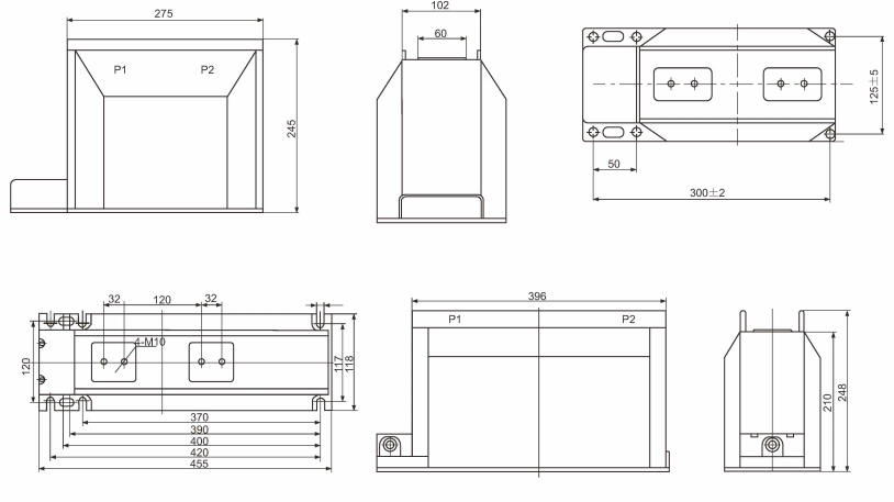
Outline and Dimensions of Installation
FAQs for LZZBJ12-10 Current Transformer
- What applications are suitable for the LZZBJ12-10 current transformer?
The LZZBJ12-10 is ideal for metering and protective relaying in indoor power systems with a rated voltage of 10kV or below and a frequency range of 50Hz to 60Hz. - How does the epoxy resin insulation enhance the transformer’s performance?
The epoxy resin provides superior insulation, resistance to humidity and pollution, and ensures stable performance under varying environmental conditions. - What safety precautions are required during operation?
The secondary circuit must remain closed during operation to avoid the generation of high voltage, which can pose safety risks. - Can the LZZBJ12-10 be customized for specific operational needs?
Yes, the transformer can be customized for unique current ratios, accuracy classes, or special environmental conditions to meet specific requirements. - What are the primary technical specifications of the LZZBJ12-10?
The transformer features a rated insulation level of 12/42/75kV, secondary currents of 5A or 1A, and primary current ratings ranging from 20A to 3000A. - Is the transformer suitable for polluted environments?
It is designed for pollution level II environments. For more severe conditions, additional protection or customization may be required.
- A Discussion on the Saturation Point of Current Transformers: Transformer Protection and Current Protection
- Number of Permissible Grounding Points in the Secondary Circuit of Voltage Transformers
- Introduction to Combined Transformers and Their Classification
- 3 Voltage Transformer Faults and Solutions: Ensuring Accurate Measurement and Protection
- Working Principle of Zero-Sequence Current Transformers
- Causes of 35KV Current Transformer Damage
