Overview
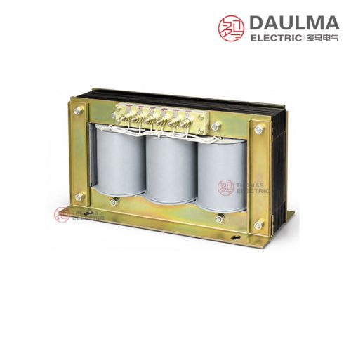
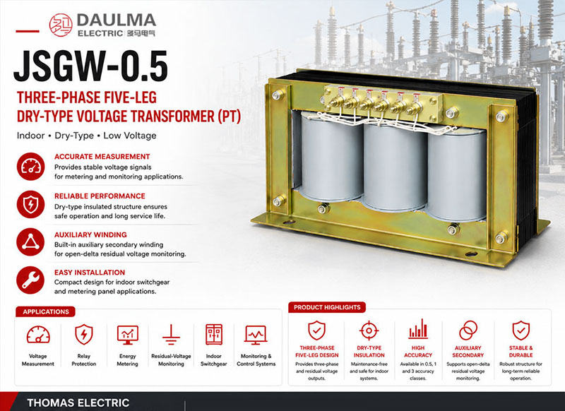
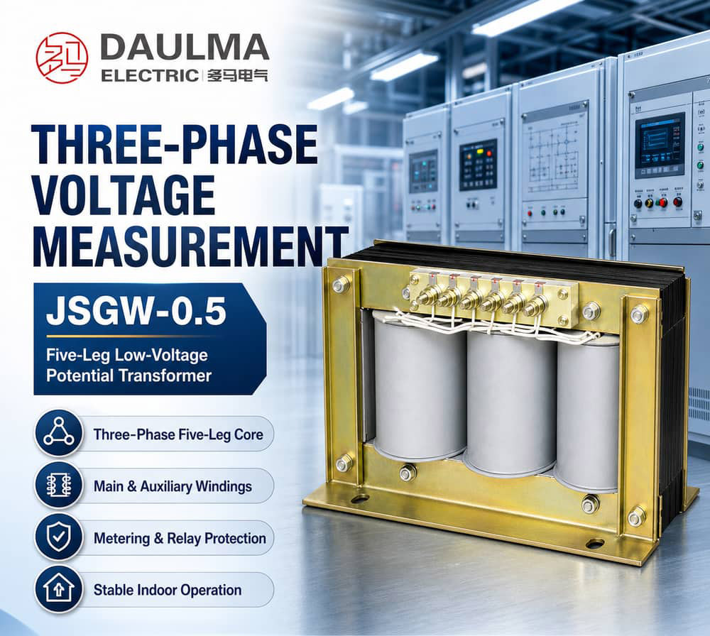
The JSGW-0.5 dry-type low-voltage potential transformer is an indoor three-phase five-leg voltage transformer engineered for precise voltage measurement, electric energy metering, and reliable relay protection in 50Hz AC power systems. It delivers stable, proportional secondary voltage signals to measuring instruments, energy meters, and protection relays, ensuring accurate system monitoring and control.
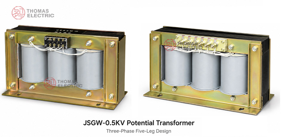
Built with a dry-type insulated structure and a three-phase five-leg magnetic core, the JSGW-0.5 includes both main and auxiliary secondary windings. This design enables standard phase-to-neutral voltage output as well as open-delta residual voltage monitoring, making it ideal for insulation supervision, abnormal voltage detection, and comprehensive protection schemes in indoor electrical installations.
Key Ratings Snapshot
| Parameter | Value |
|---|---|
| Rated frequency | 50 Hz |
| Voltage ratio (typical) | 380/sqrt(3) : 100/sqrt(3) : 100/3 V 500/sqrt(3) : 100/sqrt(3) : 100/3 V |
| Main secondary voltage | 100/sqrt(3) V |
| Auxiliary secondary voltage | 100/3 V |
| Accuracy classes | 0.5, 1, 3 |
| Rated output (VA) | 50 (0.5 class), 80 (1 class), 250 (3 class) |
| Maximum rated output | 340 VA |
| Insulation level | 0.5/3 kV |
| Core structure | Three-phase five-leg external iron core |
| Installation location | Indoor |
Model Designation

- J: Voltage transformer / potential transformer
- S: Three-phase structure
- G: Five-leg magnetic core
- W: Dry-type design
- 0.5: Voltage grade / product voltage class code
- F: Optional extended design code where applicable
Construction
The JSGW-0.5 features a robust dry-type insulated construction with no oil or liquid fill, making it safe and maintenance-free for indoor environments. Its three-phase five-leg magnetic core consists of three central limbs for primary voltage transformation and two outer return limbs that support the auxiliary winding for residual voltage output. This configuration ensures high magnetic balance and minimal zero-sequence error during normal and fault conditions.
All windings are vacuum-pressure impregnated with epoxy resin, providing excellent dielectric strength, thermal stability, and resistance to moisture and contamination. The compact mechanical design allows secure mounting inside switchgear, metering panels, and protection cabinets, with clearly marked terminals for primary, main secondary, and auxiliary secondary circuits.
Technical Parameters
Service Conditions
- Installation location: Indoor only
- Ambient temperature: -5 deg C to +40 deg C (standard)
- Relative humidity: <= 95% at 25 deg C
- Altitude: <= 1000 m above sea level
- Environment: Free from severe vibration, corrosive gases, explosive media, conductive dust, and heavy pollution
Technical Data
| Rated Voltage Ratio |
Frequency (Hz) |
Output 0.5 Class (VA) |
Output 1 Class (VA) |
Output 3 Class (VA) |
Max. Output (VA) |
Insulation Level (kV) |
|---|---|---|---|---|---|---|
| 380/sqrt(3) : 100/sqrt(3) : 100/3 | 50 | 50 | 80 | 250 | 340 | 0.5/3 |
| 500/sqrt(3) : 100/sqrt(3) : 100/3 | 50 | 50 | 80 | 250 | 340 | 0.5/3 |
Frequently Asked Questions
Q1: What environmental conditions are required for safe indoor installation?
The JSGW-0.5 requires an indoor environment free from severe vibration, corrosive gases, and conductive dust. Ambient temperature must remain between -5°C and +40°C. Confirm specific site conditions with our engineering team.
Q2: Which standard voltage ratios are available for this potential transformer?
Standard ratios include 380/√3 and 500/√3 to 100/√3 : 100/3 at 50Hz. Special voltage ratios are available subject to technical agreement. Contact our sales team for custom ratio configurations.
Q3: What is the maximum burden output for the 0.5 accuracy class?
The 0.5 class supports an output of 50 VA, while the maximum overall output reaches 340 VA. The insulation level is rated at 0.5/3 kV for standard low voltage applications.
Q4: Can we order custom installation dimensions for existing switchgear?
Yes, custom installation dimensions and output ratings can be accommodated. These modifications are subject to prior technical agreement before ordering. Please provide your dimensional requirements for factory evaluation.
Q5: How can we request custom output ratings for our project?
Custom output ratings are available subject to prior technical agreement. Please submit your specific burden requirements to our sales team for factory evaluation.
Q6: Where is this three-phase five-leg design typically applied?
This low voltage transformer suits indoor 380V and 500V distribution systems for voltage measurement and protection. It operates at a standard 50Hz frequency. Confirm system compatibility before deployment.
Q7: Why choose a five-leg core design for low voltage transformers?
The five-leg core structure provides superior magnetic flux distribution and reduces zero-sequence impedance. This ensures stable performance in ungrounded or resonant grounded low voltage systems.
Installation & Wiring
Installation Diagram
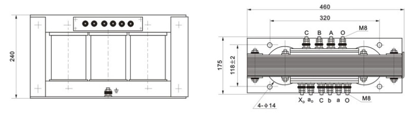
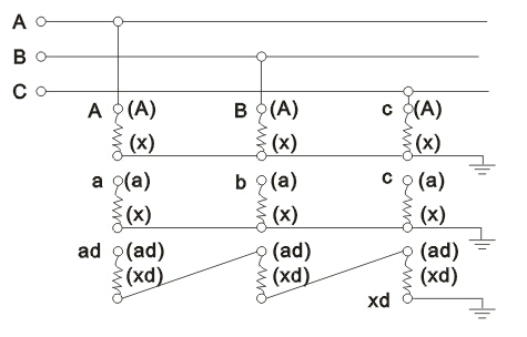
The JSGW-0.5 series is designed for fixed indoor installation within switchgear or metering cabinets. Primary terminals (A, B, C, 0), main secondary terminals (a, b, c, 0), and auxiliary secondary terminals (ad, xd) must be wired strictly according to the approved schematic diagram. Ensure correct polarity and terminal identification prior to energization.
Outline Dimensions
| Dimension | Value (mm) |
|---|---|
| Height | To be confirmed per approved drawing |
| Width | To be confirmed per approved drawing |
| Depth | To be confirmed per approved drawing |
| Mounting hole pattern | Per project-specific outline drawing |
| Terminal clearance | Sufficient for standard lugs and creepage requirements |
Selection & FAQs
Selection Guide
- Select the correct phase-to-neutral primary voltage. Choose 380/√3V or 500/√3V based on system line voltage and neutral connection.
- Define the main and auxiliary circuits separately. The main output is 100/√3V; the 100/3V auxiliary winding is for residual-voltage/open-delta-related monitoring according to the approved schematic.
- Choose the main accuracy burden. Use class 0.5 at 50VA, class 1 at 80VA or class 3 at 250VA, keeping actual connected burden within the selected rating.
- Do not treat 340VA as an accuracy output. It is the maximum output reference; confirm total thermal loading and the separately allowable auxiliary burden.
- Approve the complete three-phase connection. Verify A/B/C/0, a/b/c/0 and ad/xd polarity, neutral grounding, fuses, phase sequence, insulation, dimensions and ventilation.
Frequently Asked Questions
Q1: How do I correctly select between the 380/√3 V and 500/√3 V primary voltage options for the JSGW-0.5 in low-voltage distribution systems?
Selection depends on your system’s nominal line-to-line voltage and grounding configuration. The 380/√3 V (≈220 V phase-to-neutral) option is standard for 380 V three-phase four-wire systems commonly used in commercial and industrial facilities across Europe, Asia, and other 50 Hz regions. The 500/√3 V (≈289 V phase-to-neutral) variant applies to specialized low-voltage networks—such as certain mining, marine, or legacy industrial installations—where the system voltage is rated at 500 V line-to-line. Verify your actual system voltage under load and confirm neutral availability; mismatched selection leads to scaling errors in metering and protection functions. Always cross-check with local grid codes and equipment nameplate data before procurement.
Q2: Why can’t three single-phase potential transformers replace the JSGW-0.5 three-phase five-leg design for residual voltage monitoring?
The JSGW-0.5’s integrated five-leg magnetic core provides a dedicated zero-sequence flux path through its two outer limbs, enabling accurate and stable 100/3 V auxiliary output during ground faults or unbalanced conditions. Three discrete single-phase VTs lack this coupled magnetic structure, resulting in poor zero-sequence response due to air-core coupling limitations and inconsistent saturation characteristics. This compromises insulation monitoring reliability and may cause false tripping or failure to detect high-impedance earth faults. Additionally, separate units require more panel space, complex grounding coordination, and individual fusing—increasing installation error risk and lifecycle cost. The JSGW-0.5’s monolithic design ensures phase coherence, thermal balance, and compliance with IEC 61869-3 for combined measurement and protection applications.
Q3: What are the critical installation precautions to avoid performance degradation or safety hazards with the JSGW-0.5?
Key precautions include: (1) Strict adherence to terminal labeling—primary (A,B,C,0), main secondary (a,b,c,0), and auxiliary (ad,xd)—to prevent polarity reversal, which distorts residual voltage signals; (2) Never leave secondaries open-circuited during operation—always connect burden or short via test terminals per IEC 61869; (3) Ensure the neutral point of the main secondary winding is solidly grounded at one point only to avoid circulating currents; (4) Verify phase sequence matches system rotation to maintain vector accuracy; (5) Confirm cabinet ventilation meets thermal requirements—dry-type units like the JSGW-0.5 rely on natural convection, and restricted airflow above 40°C ambient reduces insulation life; (6) Use approved outline drawings for mounting—dimensional tolerances affect creepage and clearance compliance per IEC 60664.
Q4: How should I interpret the rated output values (e.g., 50 VA at class 0.5) versus the maximum output of 340 VA when sizing connected loads?
The rated outputs—50 VA (class 0.5), 80 VA (class 1), and 250 VA (class 3)—define the burden range within which the JSGW-0.5 maintains its declared accuracy under IEC 61869-3. Exceeding these burdens degrades measurement precision but does not immediately damage the unit. The 340 VA figure represents the thermal limit—the maximum total apparent power (main + auxiliary windings combined) the transformer can sustain continuously without overheating, based on 130°C hotspot temperature rise. However, operating near 340 VA voids accuracy guarantees. For example, if using class 0.5 for revenue metering, ensure total connected burden (including lead resistance) ≤50 VA. The auxiliary winding’s burden must be accounted separately; typical residual circuits draw <10 VA, but confirm with relay/meter specs. Always perform a burden calculation including wiring impedance.
Q5: Can the JSGW-0.5 support both metering (class 0.5) and protection (class 3) functions simultaneously on the same unit?
Yes, but not on the same secondary winding. The JSGW-0.5 has one main secondary winding (100/√3 V) that must be assigned a single accuracy class per application—either class 0.5 for metering or class 3 for protection—not both concurrently. To serve dual purposes, you would need either: (a) two separate main secondaries (not available on standard JSGW-0.5), or (b) use the main winding for one function (e.g., class 0.5 metering) and derive protection signals from external devices fed by the same winding—but this risks accuracy loss if burden exceeds 50 VA. Alternatively, some utilities use class 1 (80 VA) as a compromise. The auxiliary (100/3 V) winding is strictly for residual voltage functions and cannot substitute for protection-grade phase voltage signals. Clarify functional segregation during specification to avoid compliance issues with IEC 62053 or IEEE C57.13.
Q6: What customization options are available for the JSGW-0.5 beyond the standard 380/√3 V and 500/√3 V ratios?
Per the manufacturer’s technical agreement clause, customizations include non-standard voltage ratios (e.g., 400/√3 V, 440/√3 V), adjusted secondary voltages (e.g., 110/√3 V), modified accuracy/burden combinations (e.g., class 0.2 at 30 VA), and extended terminal configurations. However, changes to core geometry or insulation level (fixed at 0.5/3 kV) are typically not feasible due to the standardized five-leg dry-type construction. Lead time for customized units increases by 4–8 weeks versus standard models, and minimum order quantities may apply. Always request a type-test report for non-standard variants to verify performance against IEC 61869. Note: Custom dimensions require approval of outline drawings prior to cabinet fabrication—never assume interchangeability.
Q7: How does ambient temperature and altitude impact the JSGW-0.5’s performance and derating requirements?
The JSGW-0.5 is rated for -5°C to +40°C ambient and ≤1000 m altitude. Above 1000 m, dielectric strength decreases by ~1% per 100 m, requiring derating or special insulation verification—though uncommon for indoor LV applications. More critically, sustained operation above 40°C ambient reduces thermal margin; epoxy-resin insulation systems (typically Class B, 130°C) experience accelerated aging. At 45°C ambient, continuous output should be derated by ~10–15% to maintain hotspot limits. Conversely, below -5°C, thermal cycling may stress impregnation integrity, though dry-type units generally tolerate cold better than oil-filled types. Humidity ≤95% at 25°C is acceptable due to vacuum-pressure impregnation, but condensation during rapid temperature swings must be prevented via cabinet heaters or sealed enclosures in tropical climates.
Q8: What are common troubleshooting steps if the auxiliary (100/3 V) residual voltage output shows abnormal readings during commissioning?
Abnormal residual voltage (e.g., >5 V during normal operation) typically stems from: (1) Incorrect auxiliary winding connection—verify ad/xd terminals form a closed open-delta loop with no neutral tie; (2) Phase sequence or polarity errors in main secondaries—use a phasing meter to confirm A-a, B-b, C-c alignment; (3) Unbalanced system voltages exceeding 2%—measure primary phase-to-neutral voltages; (4) Grounding issues—ensure only one grounding point exists on the main secondary neutral; (5) Burden mismatch—excessive load on auxiliary winding (>10–15 VA) distorts waveform. Isolate the issue by disconnecting all auxiliary loads and measuring open-circuit voltage; it should be <1–2 V in a balanced, healthy system. If fault persists, check for core saturation due to DC offset or harmonics using a power quality analyzer. Never operate with auxiliary terminals shorted—this can overheat the winding.