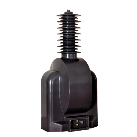
Executive Summary
Ferroresonance in voltage transformers (VTs) is a dangerous phenomenon that can cause sustained overvoltages, equipment damage, and system outages. Proper selection and application of damping resistors is the most effective mitigation technique. This technical note examines ferroresonance mechanisms and provides practical damping resistor design guidelines.
Understanding Ferroresonance
The Phenomenon
Ferroresonance occurs when the nonlinear inductance of a VT’s magnetic core interacts with system capacitance to create sustained oscillations. Unlike linear resonance, ferroresonance can occur at multiple frequencies and can persist indefinitely once initiated.
Typical Triggers
- Single-pole switching: Energizing one phase while others remain open
- Fault clearing: Single-line-to-ground fault interruption
- Capacitive coupling: From adjacent energized circuits
- Grading capacitance: In circuit breaker interrupters
Consequences
- Overvoltage: 2-5× nominal voltage sustained for seconds to hours
- VT damage: Core saturation causes overheating, insulation failure
- Arrester failure: Surge arresters may fail from sustained overvoltage
- System instability: False relay operation, equipment stress
Ferroresonance Circuit Model
Basic Circuit
The ferroresonant circuit consists of:
- Nonlinear inductance (L): VT magnetizing inductance (varies with saturation)
- Capacitance (C): System capacitance (bus, cable, grading caps)
- Resistance (R): Circuit losses (often insufficient to damp oscillations)
Resonance Conditions
Ferroresonance is most likely when:
- Capacitance range: 100 pF to 10 μF (depends on VT characteristics)
- Voltage level: More common at 3-35kV (distribution/sub-transmission)
- VT connection: Grounded-wye VTs on ungrounded or high-impedance grounded systems
- Low load: Lightly loaded systems have less natural damping
Damping Resistor Design
Resistor Location
Option 1: Open-Delta Connection (Most Common)
For three-phase VTs with broken-delta secondary:
- Connection: Resistor across open-delta terminals
- Advantage: Simple, effective, no impact on normal operation
- Typical values: 50-200Ω, 200-500W
Option 2: Primary Neutral Resistor
- Connection: Between VT primary neutral and ground
- Advantage: Directly dampens primary circuit oscillations
- Disadvantage: Requires high-voltage resistor, safety concerns
- Typical values: 500-2000Ω per phase, sized for continuous duty
Option 3: Secondary Burden Resistor
- Connection: Permanent burden on one or more secondary windings
- Advantage: Simple, uses standard resistors
- Disadvantage: Increases VT burden, affects accuracy if on metering winding
- Typical values: Sized to draw 10-20% of VT rated output
Resistance Value Calculation
For Open-Delta Connection
Formula: R = V_secondary² / P_damping
Where:
- V_secondary = secondary voltage (typically 110V or 120V for open-delta)
- P_damping = required damping power (typically 200-500W)
Example: 110V open-delta, 300W damping
- R = 110² / 300 = 12100 / 300 = 40.3Ω
- Select standard value: 40Ω or 47Ω
- Power rating: ≥ 300W (use 400W for margin)
For Primary Neutral Resistor
Formula: R = V_phase / I_damping
Where:
- V_phase = system phase-to-ground voltage
- I_damping = desired damping current (typically 0.5-2A)
Example: 35kV system (20.2kV phase-ground), 1A damping
- R = 20200 / 1 = 20.2kΩ
- Power rating: P = V × I = 20200 × 1 = 20.2kW (for fault duration)
- Note: Primary resistors typically rated for short-time duty (10-60 seconds)
Resistor Specifications
Material Selection
| Resistor Type | Power Rating | Temperature Rating | Application |
|---|---|---|---|
| Wire-wound | 100-1000W | Up to 350°C | Open-delta, secondary burden |
| Grid resistor | 1-50kW | Up to 500°C | Primary neutral (short-time) |
| Ceramic | 10-500W | Up to 400°C | Open-delta, compact installations |
| Stainless steel | 500W-10kW | Up to 600°C | Primary neutral, outdoor |
Environmental Considerations
- Indoor installation: Standard IP20 enclosure, adequate ventilation
- Outdoor installation: IP65 minimum, UV-resistant housing, stainless steel hardware
- Temperature: Resistor surface can reach 300-400°C during operation—maintain clearance from combustible materials
- Mounting: Elevated mounting for air circulation; avoid enclosed spaces
Application Guidelines
For New Installations
- Assess ferroresonance risk: System configuration, capacitance, VT type
- Specify damping resistor: Include in VT procurement documents
- Install during commissioning: Verify connection and resistance value
- Document: Record resistor value, location, and power rating
For Existing Installations (Retrofit)
- Survey VTs: Identify VTs without damping resistors
- Risk assessment: Review system history for ferroresonance incidents
- Design retrofit: Select appropriate resistor type and location
- Schedule installation: Plan outage for safe installation
- Verify operation: Test resistor continuity and connection
Alternative Mitigation Techniques
1. VT Selection
- Anti-ferroresonance VTs: Designed with core characteristics that reduce ferroresonance risk
- Capacitive VTs (CVTs): Not susceptible to ferroresonance (different operating principle)
- Three-limb core design: Better magnetic coupling reduces risk
2. System Grounding
- Low-impedance grounding: Reduces neutral shift that can trigger ferroresonance
- Grounding transformer: Zig-zag or wye-delta transformer provides ground reference
3. Active Suppression
- Electronic damping: Power electronics inject counter-oscillation
- Advantage: Only activates when needed, no continuous losses
- Disadvantage: Higher cost, more complex
Field Testing
Resistor Verification
- [ ] Measure resistance: Within ±10% of nameplate value
- [ ] Insulation resistance: > 100 MΩ at 1000V DC (resistor to ground)
- [ ] Visual inspection: No cracks, discoloration, or loose connections
- [ ] Connection integrity: Torque terminals to specification
System Testing (Energization)
- [ ] Monitor VT secondary voltage during initial energization
- [ ] Check for sustained overvoltage (> 1.5× nominal)
- [ ] Verify resistor heating during switching operations
- [ ] Document normal operating temperature (infrared thermometer)
Maintenance
Annual Inspection
- [ ] Visual inspection for physical damage, corrosion, loose connections
- [ ] Infrared thermography during normal operation (baseline temperature)
- [ ] Verify resistor value (offline measurement if possible)
- [ ] Check enclosure integrity (outdoor installations)
After Ferroresonance Event
- [ ] Inspect resistor for thermal damage (discoloration, warping)
- [ ] Measure resistance (may have changed due to thermal stress)
- [ ] Check VT for damage (insulation resistance, ratio test)
- [ ] Replace resistor if any doubt about integrity
Engineering Checklist
Design Phase
- [ ] Assess ferroresonance risk for system configuration
- [ ] Specify damping resistor in VT procurement documents
- [ ] Calculate resistor value and power rating
- [ ] Select appropriate resistor type for environment
- [ ] Plan mounting location with adequate ventilation
Installation Phase
- [ ] Verify resistor value before installation
- [ ] Use proper torque on all connections
- [ ] Maintain clearance from combustible materials
- [ ] Label resistor with value, power rating, and purpose
Commissioning Phase
- [ ] Measure resistance after installation
- [ ] Verify correct connection (open-delta polarity, neutral grounding)
- [ ] Monitor during initial energization
- [ ] Document baseline operating temperature
Conclusion
Ferroresonance is a well-understood phenomenon with proven mitigation techniques. Damping resistors are the most practical and cost-effective solution for most installations. Engineers who properly design, install, and maintain damping resistors will prevent ferroresonance-related equipment damage and system outages.
Critical recommendation: For all grounded-wye VTs on ungrounded or high-impedance grounded systems at 3-35kV, specify damping resistors as a mandatory requirement. The cost of a resistor (< $500) is negligible compared to the cost of VT replacement and system outage.
Technical Reference: IEC 61869-3, IEEE C57.13, CIGRE WG 33.01, EPRI TR-102626