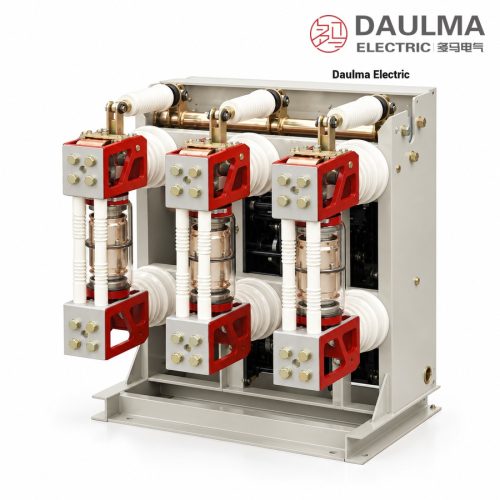
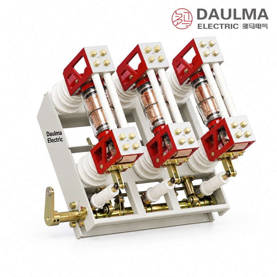
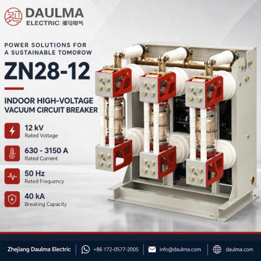
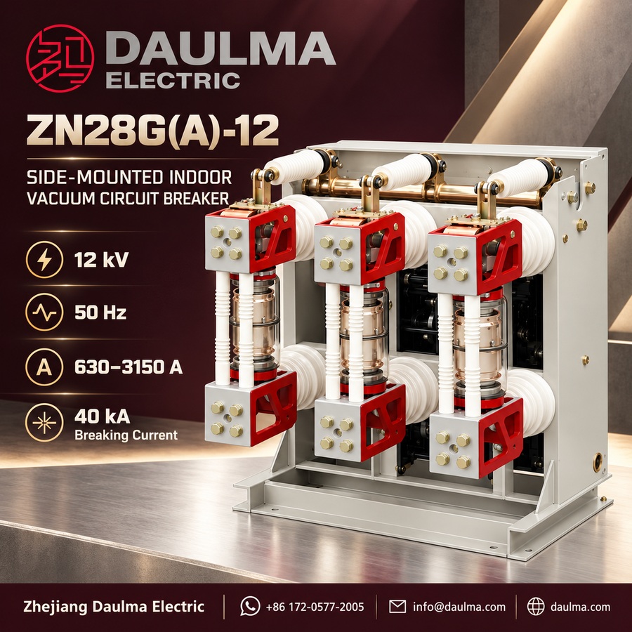
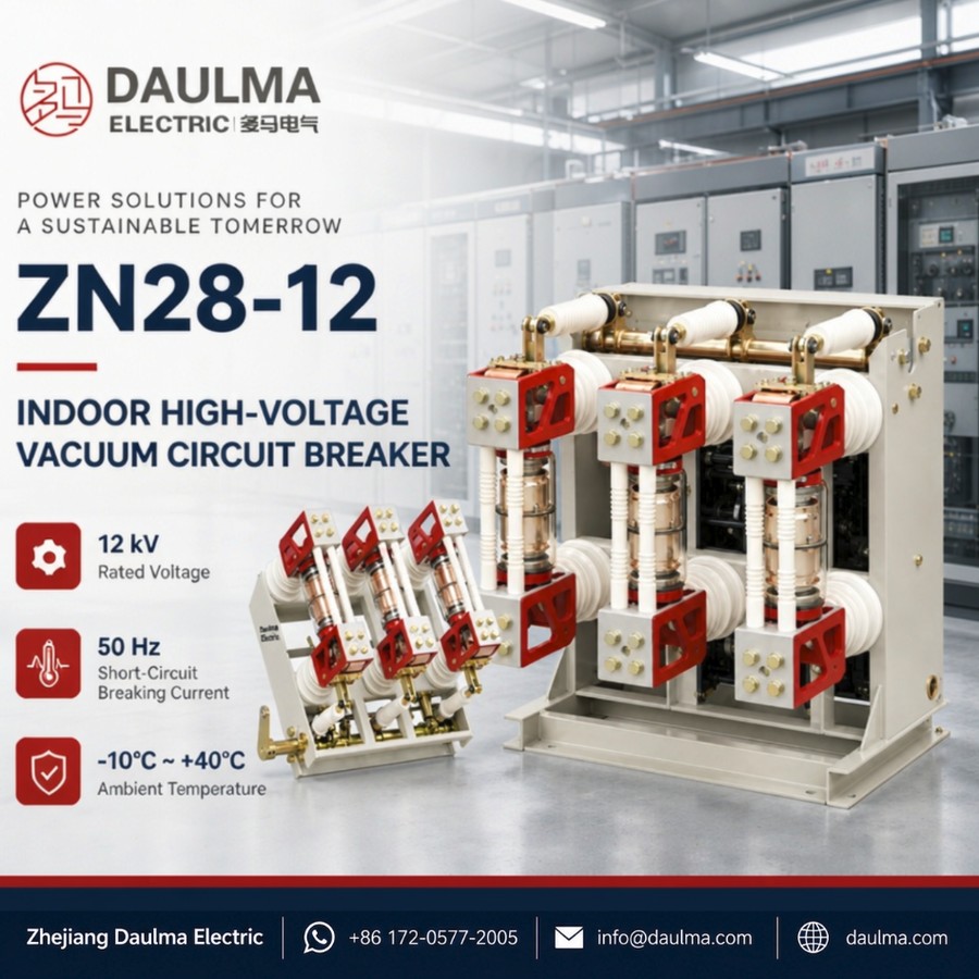
The ZN28G(A)-12 is a three-phase 50 Hz indoor high voltage vacuum circuit breaker rated 12 kV, of side-mounted pole-unit construction, used to control and protect power plants, substations and industrial and mining distribution systems. It can be installed in both handcart-type and fixed-type metal-enclosed switchgear, and thanks to vacuum interruption it is especially suitable for frequent operation.
The “G” designation denotes the fixed type and “A” the suspended type. The breaker may be driven by a CT17 or CT19 spring energy-storage mechanism or a CD17 electromagnetic mechanism, so it can be matched to the available control supply. Rated current ranges from 630 to 3150 A with a rated short-circuit breaking current of 20, 31.5 or 40 kA and a 4 s short-time withstand rating.
Model Designation
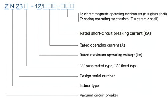
The type is marked as ZN 28 □ – 12 / □□□ – □□□:
- Z — vacuum
- N — indoor use
- 28 — design number
- □ — mounting form: “A” suspended, “G” fixed
- 12 — rated voltage kV
- □□□ — rated current A
- □□□ — rated short-circuit breaking current kA
- D / T — D for electromagnetic mechanism (B glass envelope), T for spring mechanism (T ceramic envelope)
Example: ZN28G-12/1250-31.5 denotes a 12 kV fixed-type side-mounted indoor vacuum circuit breaker with 1250 A rated current and 31.5 kA rated short-circuit breaking current.
Performance Advantages
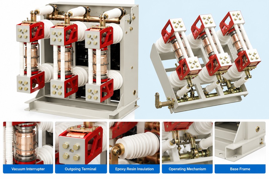
- Side-mounted pole units, fixed or handcart. The three vacuum-interrupter pole units are mounted side by side on a common frame, so the same breaker fits handcart-type and fixed-type switchgear, with the “G” fixed and “A” suspended variants.
- Choice of spring or electromagnetic mechanism. A CT17 / CT19 spring energy-storage mechanism or a CD17 electromagnetic mechanism can be specified to match the control supply, giving reliable operation for frequent switching.
- High breaking capacity and long life. Breaking currents up to 40 kA, a 42 / 48 kV power-frequency and 75 / 85 kV impulse insulation level, a 10000-operation mechanical life and 30 (50) rated short-circuit breaking operations.
Technical Parameters
Service Conditions
- Ambient temperature: upper +40℃, lower -10℃ (down to -30℃ during storage and transport)
- Altitude: not above 1000 m (higher altitude raises the rated insulation level accordingly)
- Seismic intensity: not above intensity 8
- Humidity: daily average ≤ 95%, monthly average ≤ 90%
- Environment: no fire, explosion, serious pollution, chemical corrosion or violent vibration
Main Technical Parameters
| No. | Item | Unit | Data |
|---|---|---|---|
| 1 | Rated voltage | kV | 12 |
| 2 | Rated current | A | 630 – 3150 |
| 3 | Rated short-circuit breaking current | kA | 20 / 31.5 / 40 |
| 4 | Rated short-circuit making current (peak) | kA | 50 / 80 / 100 |
| 5 | Rated peak withstand current (dynamic stability) | kA | 50 / 80 / 100 |
| 6 | Rated short-time withstand current (thermal stability, r.m.s.) | kA | 20 / 31.5 / 40 |
| 7 | Rated short-time withstand duration | s | 4 |
| 8 | Number of rated short-circuit breaking operations | times | 30 (50) |
| 9 | Total breaking time (electromagnetic mechanism) | ms | < 80 |
| 10 | Rated operating sequence | — | O – 0.3 s – CO – 180 s – CO |
| 11 | 1 min power-frequency withstand voltage (r.m.s.) | kV | 42 to earth / between phases; 48 across the break |
| 12 | Rated lightning impulse withstand voltage (peak) | kV | 75 to earth / between phases; 85 across the break |
| 13 | Mechanical life | operations | 10000 |
Standards
- Designed and tested to GB/T 1984 (AC high-voltage circuit breakers) and IEC 62271-100
- Manufacturing and inspection per DL/T 403 (indoor high-voltage AC vacuum circuit breakers)
Installation & Wiring
Installation and Mounting
The ZN28G(A)-12 is a side-mounted indoor vacuum circuit breaker whose three pole units are fixed side by side on a common frame. The “G” fixed type is bolted directly into fixed-type metal-enclosed switchgear, while the “A” suspended variant and the handcart mounting allow the breaker to be used in handcart-type cubicles. The primary circuit connects to the busbar through the terminal clamps and the secondary circuit is wired to the control, protection and measurement loops through the terminal block. The breaker frame and the switchgear body must be reliably earthed before commissioning, and all mechanical interlocks and the mechanism travel must be verified before operation.
Outline and Installation Dimensions
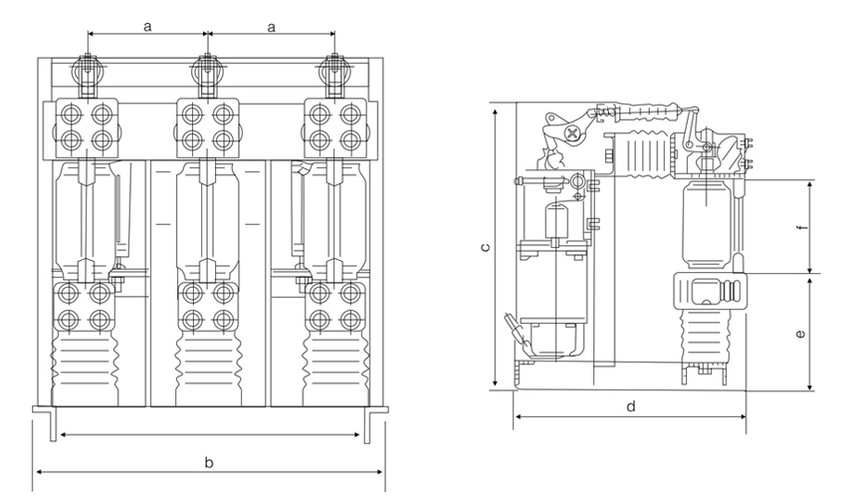
The outline drawing marks the main dimensions with the symbols below; the numerical values are given on the approved outline drawing supplied with each order and are not reproduced here.
| Symbol | Dimension |
|---|---|
| a | Pole-unit / phase spacing (front view) |
| b | Overall width of the frame (front view) |
| c | Overall height (side view) |
| d | Overall depth (side view) |
| e | Mechanism / lower section height (side view) |
| f | Upper section height (side view) |
Applications
- Indoor 12 kV MV switchgear in power plants, substations and industrial / mining distribution
- Control and protection of feeder and transformer circuits requiring frequent operation
- Fixed-type and handcart-type metal-enclosed cubicles (G fixed, A suspended variants)
Selection & FAQs
Selection Guide
- Rated voltage and insulation level. Choose the 12 kV version and check that the 42 / 48 kV power-frequency and 75 / 85 kV impulse withstand levels match the busbar insulation.
- Rated current. Select from 630 to 3150 A by the maximum continuous load current, considering temperature rise and cubicle fit.
- Rated short-circuit breaking current. Select 20, 31.5 or 40 kA by the prospective short-circuit current at the installation point, with the matched making / peak-withstand current (50 / 80 / 100 kA) and the 4 s short-time rating.
- Operating mechanism. Specify a CT17 / CT19 spring energy-storage mechanism or a CD17 electromagnetic mechanism to suit the available control supply.
- Mounting form. Choose the “G” fixed type for fixed cubicles or the “A” suspended / handcart mounting for withdrawable cubicles; specify the matching switchgear.
- Compare neighbouring designs. For outdoor applications see Outdoor Vacuum Circuit Breakers; for switching without short-circuit duty see HV Load Break Switches.
FAQs
Q1: What does the type designation ZN28G(A)-12 mean?
Z denotes a vacuum breaker, N indoor use and 28 the design number; the letter after it gives the mounting form (G fixed, A suspended), 12 is the rated voltage in kV, and the following groups give the rated current in amperes and the rated short-circuit breaking current in kiloamperes.
Q2: What operating mechanisms are available?
The ZN28G-12 series can be fitted with a CT17 or CT19 spring energy-storage mechanism or a CD17 electromagnetic mechanism, so the operating supply can be matched to the substation control power.
Q3: What is the insulation level of the 12 kV breaker?
The 1 min power-frequency withstand voltage is 42 kV to earth and between phases and 48 kV across the break; the rated lightning impulse withstand voltage is 75 kV to earth and between phases and 85 kV across the break.
Q4: Which rated currents and breaking currents are available?
Rated current ranges from 630 to 3150 A. The rated short-circuit breaking current is 20, 31.5 or 40 kA, with a matching making and peak-withstand current of 50, 80 or 100 kA and a short-time withstand of the same value as the breaking current for 4 s.
Q5: Where can the ZN28G(A)-12 be installed?
It is a side-mounted breaker that can be installed in both handcart-type and fixed-type metal-enclosed switchgear; the G fixed and A suspended variants cover the two mounting styles, and it is suited to frequent operation.
Q6: What data do I need to provide when ordering?
Please state rated voltage, rated current, rated short-circuit breaking current, the mounting form (G fixed or A suspended), the mechanism type (spring CT17 / CT19 or electromagnetic CD17), the control supply voltage, the switchgear cubicle type and any special service conditions.