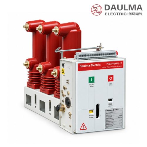
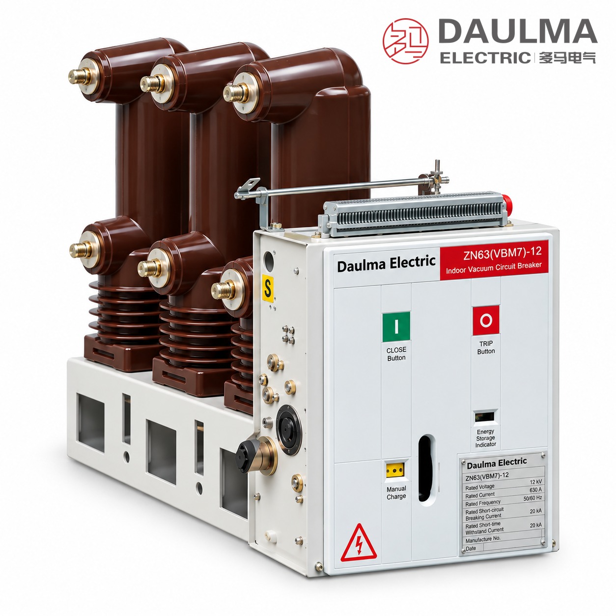
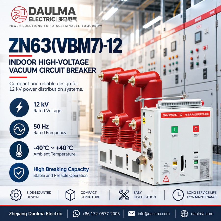
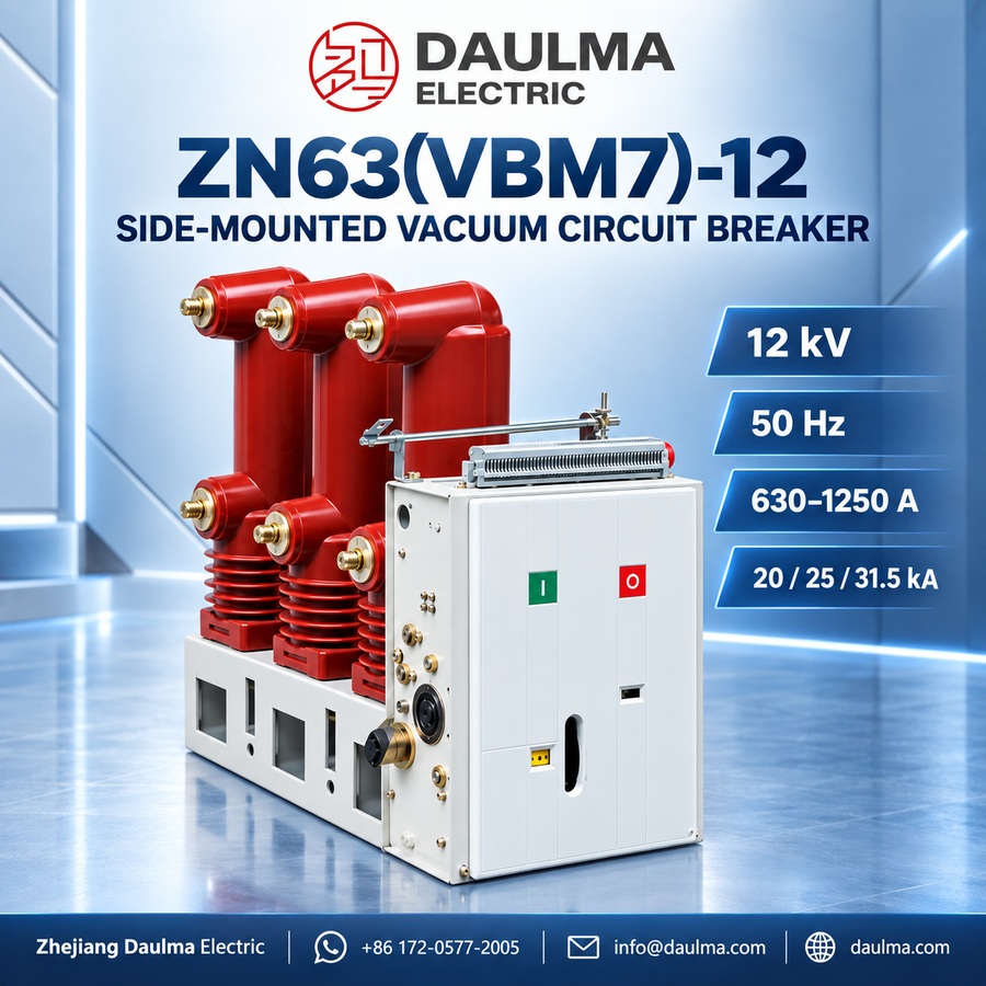
The ZN63(VBM7)-12 is a three-phase 50 Hz indoor high voltage vacuum circuit breaker rated 12 kV, used as the control and protection unit of power networks and of power equipment in industrial and mining enterprises. Owing to the advantages of vacuum interruption it is especially suitable for duty that requires frequent operation at rated current, or the repeated interruption of short-circuit currents.
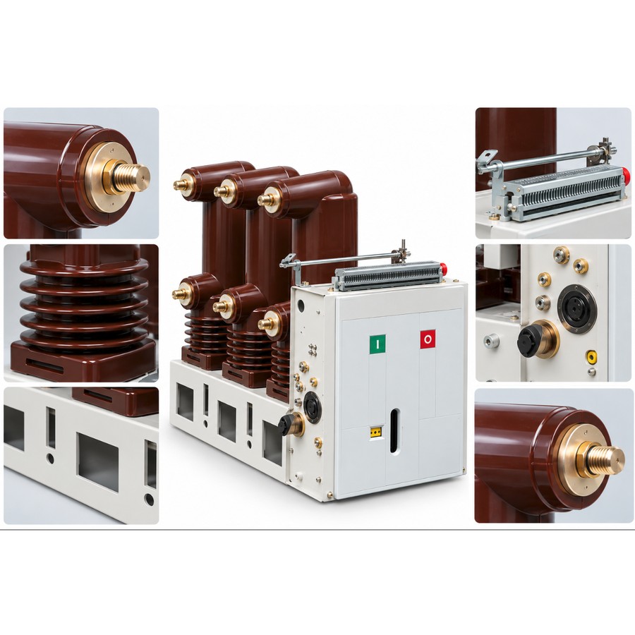
The breaker is a side-mounted, fixed-type unit intended mainly for fixed-pattern metal-enclosed switchgear. It may be used on its own or within ring-network supply, box-type substations and other non-standard supply systems. The VBM7 double-stable permanent-magnet operating mechanism and the vacuum interrupter are integrated on a common frame, so the drive train is short, the number of mechanical parts is small and the maintenance workload is minimal.
Model Designation
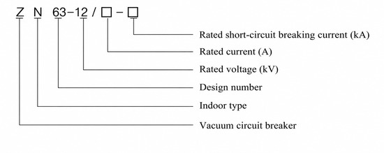
The type is marked as ZN 63-12 / □ – □:
- Z — vacuum
- N — indoor use
- 63 — design number
- 12 — rated voltage kV
- / □ — rated current A
- – □ — rated short-circuit breaking current kA
Example: ZN63(VBM7)-12 / 1250 – 31.5 denotes a 12 kV indoor vacuum circuit breaker with 1250 A rated current, 31.5 kA rated short-circuit breaking current and a VBM7 permanent-magnet mechanism. ZN63 is the GB type designation of this series; VS1 is the equivalent common trade name.
Performance Advantages
- Operating mechanism. The VBM7 double-stable permanent-magnet mechanism uses permanent magnets to hold the closed and open positions, so drive parts are far fewer than a spring mechanism, the transmission chain is shorter and reliability and mechanical life are greatly improved.
- Interrupting medium. The arc is extinguished in a sealed vacuum interrupter, giving a long electric life, no fire or explosion risk and no frequent overhaul.
- Side-mounted fixed unit. The compact side-mounted structure fits fixed-pattern metal-enclosed switchgear and supports electric, manual and remote operation with the required interlocking.
Technical Parameters
Service Conditions
- Ambient temperature: upper +40℃, lower -40℃
- Altitude: not above 1000 m (higher altitude raises the rated insulation level accordingly)
- Seismic intensity: not above intensity 8
- Humidity: daily average ≤ 95%, monthly average ≤ 90%
- Environment: no fire, explosion, serious pollution, chemical corrosion or violent vibration
Current and Breaking Ratings
| Item | Unit | 20 kA | 25 kA | 31.5 kA |
|---|---|---|---|---|
| Rated current | A | 630–1250 | 1250 | 1250 |
| Rated short-circuit breaking current | kA | 20 | 25 | 31.5 |
| Rated short-circuit making current (peak) | kA | 50 | 63 | 80 |
| Rated peak withstand current | kA | 50 | 63 | 80 |
| Rated short-time withstand current (4 s) | kA | 20 | 25 | 31.5 |
Main Technical Parameters
| No. | Item | Unit | Data |
|---|---|---|---|
| 1 | Rated voltage | kV | 12 |
| 2 | Rated frequency | Hz | 50 |
| 3 | 1 min power-frequency withstand voltage | kV | 42 (48 across the open contacts) |
| 4 | Lightning impulse withstand voltage (peak) | kV | 75 (85 across the open contacts) |
| 5 | Rated operating sequence | — | O – 0.3 s – CO – 180 s – CO |
| 6 | Mechanical life | operations | 10000 |
| 7 | Breaking operations at rated short-circuit current | times | 50 |
| 8 | Closing / opening voltage of mechanism | V | AC/DC 220, 110 |
| 9 | Contact gap | mm | 11 ± 1 |
| 10 | Over-travel (contact spring compression) | mm | 3.5 ± 0.5 |
| 11 | Three-phase open / close bounce time | ms | ≤ 2 |
| 12 | Average opening / closing speed | m/s | 1.1 ± 0.2 / 0.6 ± 0.2 |
| 13 | Opening time (max / min operating voltage) | s | ≤ 0.05 / ≤ 0.08 |
| 14 | Closing time | s | 0.1 |
| 15 | Admissible contact wear accumulation | mm | 3 |
Standards
- Designed and tested to GB/T 1984 (AC high-voltage circuit breakers) and IEC 62271-100
- Manufacturing and inspection per DL/T 402
Installation & Wiring
Installation and Mounting
The ZN63(VBM7)-12 is a side-mounted, fixed-type breaker designed to be installed inside fixed-pattern metal-enclosed switchgear. Each pole is bolted to the panel through its mounting frame, the primary circuit is connected to the busbar and cable side through the static contacts or cable lugs, and the secondary circuit is wired to the control and protection loop through the terminal block. The mechanism front plate provides manual open/close controls and position indication. The breaker and its frame must be reliably earthed before commissioning.
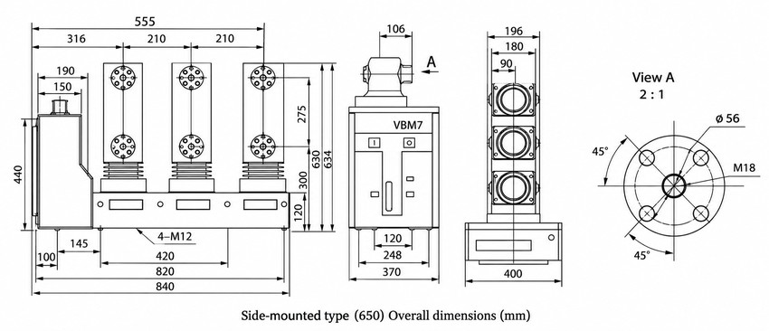
Outline and Installation Dimensions
| Item | Dimension (mm) |
|---|---|
| Overall width | 840 |
| Overall height | 634 |
| Overall depth | 400 |
| Pole center spacing | 210 |
| Base fixing | 4 × M12, hole span 820 |
| Bushing flange (View A) | Ø56 / M18 |
Applications
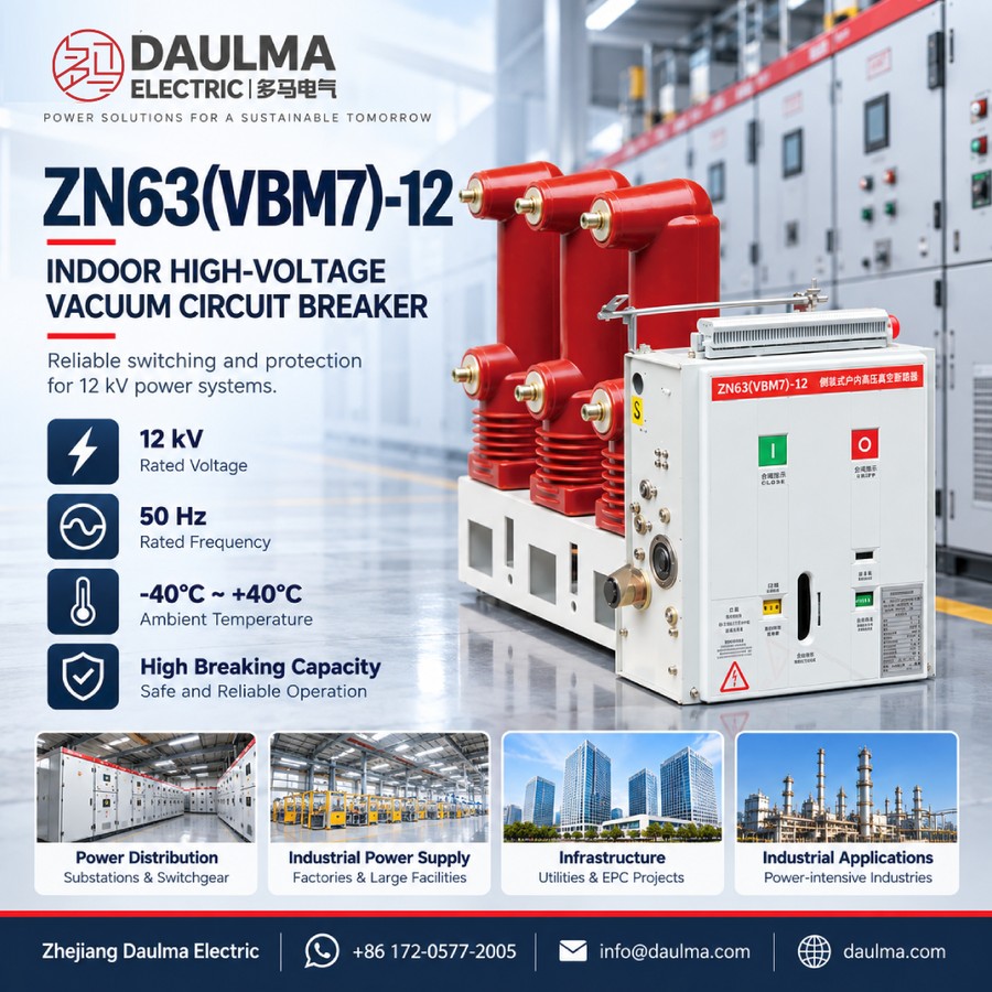
- Indoor MV switchgear in substations and industrial / mining power distribution
- Feeder protection and motor control requiring frequent operation
- Ring-network supply, box-type substations and non-standard supply systems
Selection & FAQs
Selection Guide
- Rated voltage and insulation level. Choose 12 kV for the nominal system voltage and check that the power-frequency and impulse withstand levels match the busbar insulation.
- Rated current. Select 630 or 1250 A by the maximum load current, considering temperature rise and busbar fit.
- Rated short-circuit breaking current. Select 20 / 25 / 31.5 kA by the prospective short-circuit current at the installation point, with the 4 s short-time rating.
- Operating mechanism and mounting. VBM7 permanent-magnet mechanism, side-mounted fixed unit matched to the fixed-pattern switchgear.
- Service conditions. Confirm the lower ambient temperature, altitude, seismic intensity and humidity against the actual site.
- Compare neighbouring designs. For outdoor applications see Outdoor Vacuum Circuit Breakers; for switching without short-circuit duty see HV Load Break Switches.
FAQs
Q1: What does the type designation ZN63-12 mean?
Z denotes a vacuum breaker, N indoor use, 63 the design number and 12 the rated voltage in kV; the two following boxes give rated current in amperes and rated short-circuit breaking current in kiloamperes. ZN63 is the GB type code and VS1 the equivalent trade name.
Q2: What is the difference between a permanent-magnet and a spring mechanism?
The VBM7 permanent-magnet mechanism holds the open and closed positions with permanent magnets instead of a stored spring, so it has far fewer moving parts, a shorter drive chain, higher reliability and a mechanical life of 10000 operations.
Q3: How is the side-mounted fixed unit different from a handcart breaker?
A side-mounted breaker is bolted into fixed-pattern switchgear and wired directly, whereas a handcart unit can be racked out for isolation. The fixed type is compact and lower cost where draw-out maintenance is not required.
Q4: How do I choose the rated short-circuit breaking current?
Calculate the prospective three-phase short-circuit current at the installation point and select 20, 25 or 31.5 kA to cover it, checking that the making and peak withstand currents of 50, 63 or 80 kA are also satisfied.
Q5: Can it be used for frequent operation or motor loads?
Yes. The vacuum interrupter and permanent-magnet mechanism are designed for frequent operation at rated current and repeated interruption of short-circuit currents, which suits feeder and motor duty.
Q6: What data do I need to provide when ordering?
Please state rated voltage, rated current, rated short-circuit breaking current, short-time duration, operating mechanism, the switchgear type the breaker will be mounted in, and any special service conditions.