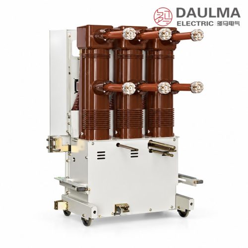
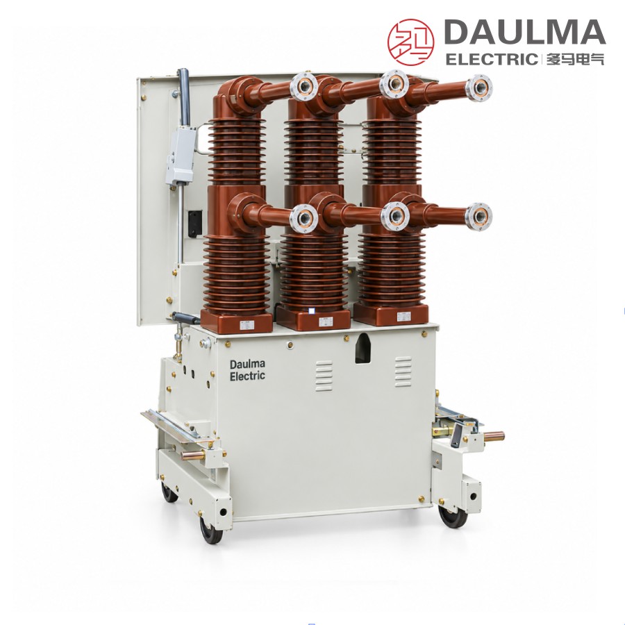
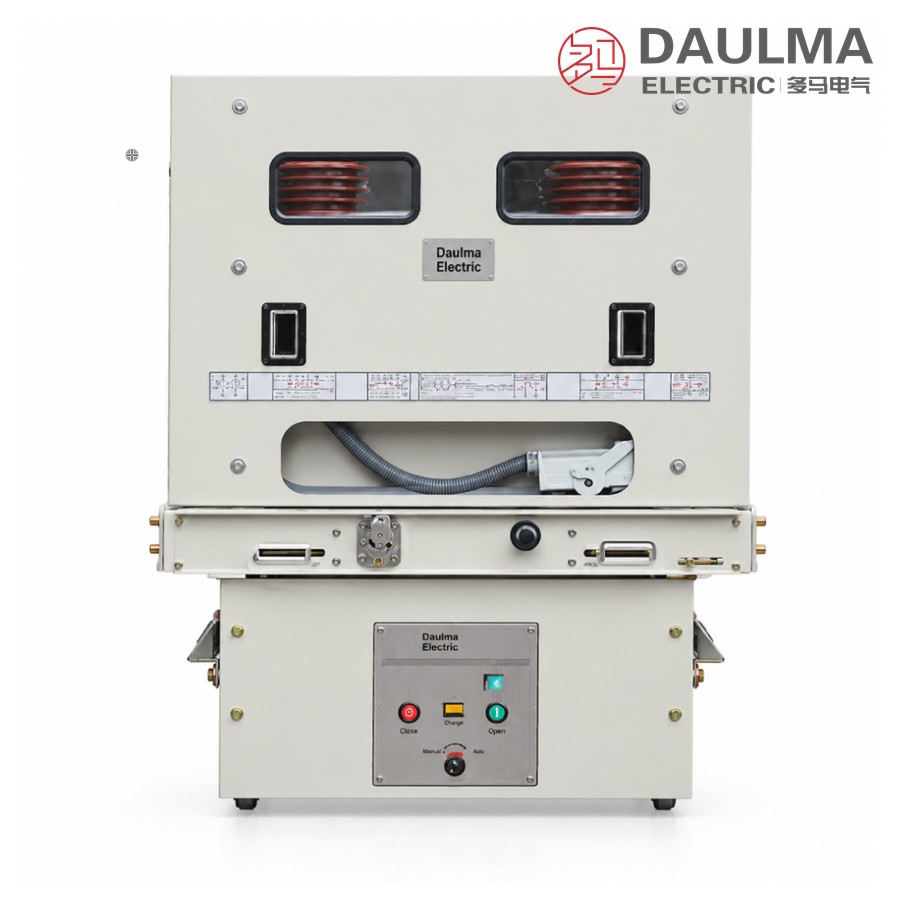
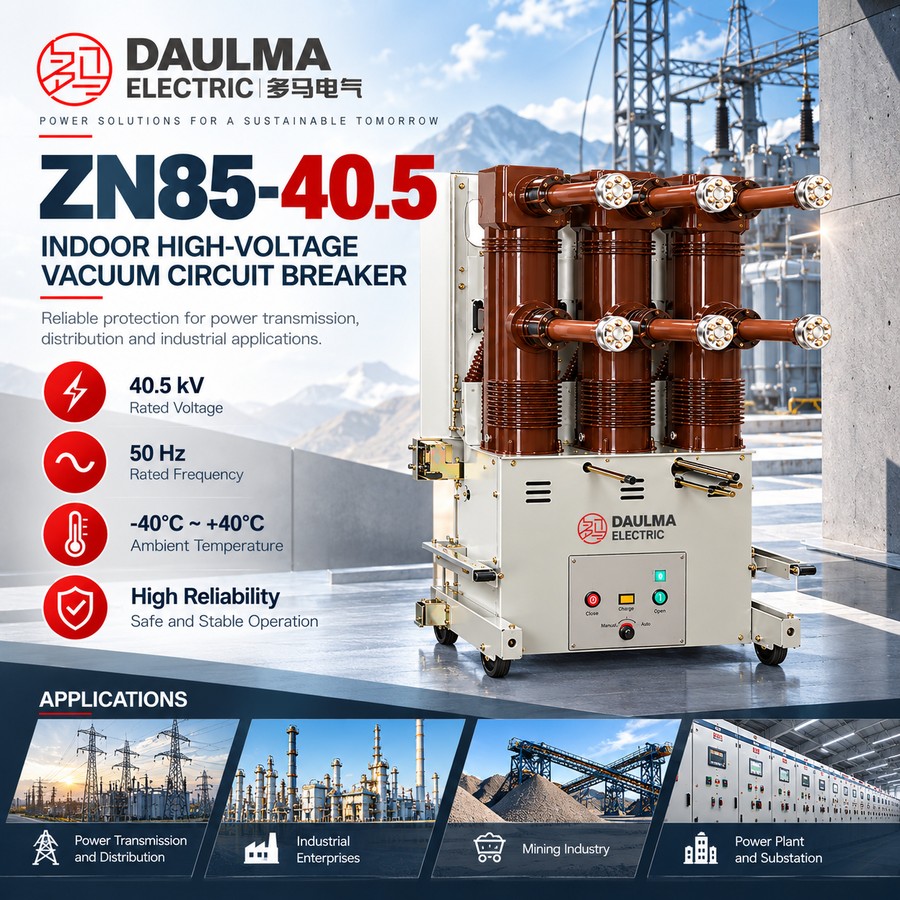
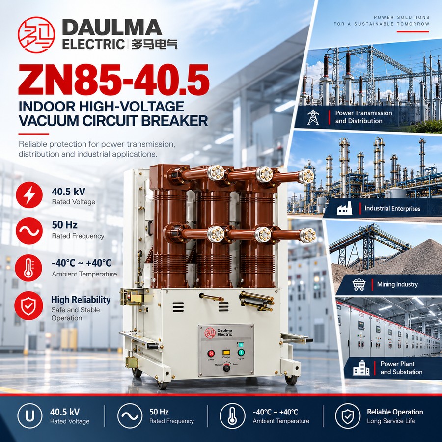
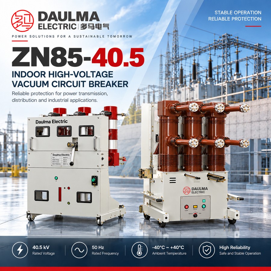
The ZN85-40.5 (type code ZN85-40.5C) is a three-phase 50 Hz handcart (withdrawable) indoor high voltage vacuum circuit breaker for 40.5 kV metal-enclosed switchgear. It is used to make, carry and break load current, overload current and short-circuit current in power plants, substations and industrial and mining distribution systems, and is well suited to duty where frequent operation is required. Vacuum interruption combined with a fully insulated, compact handcart unit gives high reliability in a small footprint.
The breaker is driven by a spring energy-storage mechanism and racks between the connected, test and disconnected positions of the switchgear, so it can be isolated or withdrawn while the cubicle stays energised. Rated current is 1250, 1600 or 2000 A with a rated short-circuit breaking current of 25 or 31.5 kA, a 4 s short-time withstand rating, and capacitor bank breaking of 630 A (single) and 400 A (back-to-back).
Model Designation
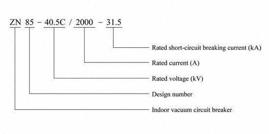
The designation ZN 85 – 40.5 C / □ – □ is decoded as:
- Z — vacuum
- N — indoor use
- 85 — design serial number
- 40.5 — rated voltage kV
- C — handcart (withdrawable) type
- / □ — rated current A
- – □ — rated short-circuit breaking current kA
Example: ZN85-40.5C/2000-31.5 denotes a 40.5 kV handcart indoor high voltage vacuum circuit breaker with 2000 A rated current and 31.5 kA rated short-circuit breaking current.
Performance Advantages
- Vacuum interruption. The arc is extinguished in a sealed vacuum interrupter, giving a high insulation level (185 kV lightning impulse / 95 kV power frequency), an electric life of 20 operations at rated short-circuit current and no fire or explosion risk.
- Withdrawable handcart unit. The breaker racks between the connected, test and disconnected positions of metal-enclosed switchgear, allowing fast isolation and replacement while the cubicle stays energised, with reliable mechanical interlocking.
- Capacitor bank and frequent-duty capability. It breaks a single capacitor bank current of 630 A and a back-to-back bank current of 400 A, and with a mechanical life of 10000 operations it suits heavily and frequently switched loads.
Technical Parameters
Service Conditions
- Ambient temperature: upper +40℃, lower -40℃
- Altitude: not above 2000 m (a higher altitude requires a correspondingly higher rated insulation level)
- Seismic intensity: not above intensity 8
- Humidity: daily average ≤ 95%, monthly average ≤ 90%
- Environment: free from fire, explosion, severe pollution, chemical corrosion and violent vibration
- Special conditions: consult the manufacturer when used outside these limits
Main Technical Parameters
| No. | Item | Unit | Data |
|---|---|---|---|
| 1 | Rated voltage | kV | 40.5 |
| 2 | Rated frequency | Hz | 50 |
| 3 | Rated current | A | 1250 / 1600 / 2000 |
| 4 | Rated short-circuit breaking current | kA | 25 / 31.5 |
| 5 | Rated short-time withstand current | kA | 25 / 31.5 |
| 6 | Rated short-circuit duration | s | 4 |
| 7 | Rated peak withstand current | kA | 63 / 80 |
| 8 | Rated short-circuit making current (peak) | kA | 63 / 80 |
| 9 | Rated lightning impulse withstand voltage (peak) | kV | 185 |
| 10 | 1 min power-frequency withstand voltage (RMS) | kV | 95 |
| 11 | Rated short-circuit breaking time | ms | < 80 |
| 12 | Rated operating sequence | — | O – 0.3 s – CO – 180 s – CO |
| 13 | Breaking operations at rated short-circuit current | times | 20 |
| 14 | Rated single capacitor bank breaking current | A | 630 |
| 15 | Back-to-back capacitor bank breaking current | A | 400 |
| 16 | Mechanical life | operations | 10000 |
| 17 | Rated operating voltage (AC/DC) | V | 110 / 220 |
Standards
- Designed and tested to GB/T 1984 (AC high-voltage circuit breakers) and IEC 62271-100
- Manufacturing and inspection per DL/T 403 (indoor high-voltage vacuum circuit breakers 3.6 to 40.5 kV)
Installation & Wiring
Installation and Mounting
The ZN85-40.5 is a handcart (withdrawable) indoor high voltage vacuum circuit breaker for metal-enclosed switchgear. The breaker is assembled onto a chassis that racks between the connected, test and disconnected positions, so it can be isolated or removed without de-energising the cubicle. The primary circuit connects to the busbar through the static contacts of the chassis, and the secondary circuit is wired to the control, protection and measurement loops through the terminal block. The breaker frame and the switchgear body must be reliably earthed before commissioning, and all mechanical interlocks must be verified before operation.
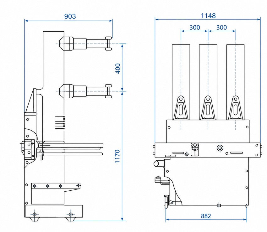
Outline and Installation Dimensions
Main outline dimensions (mm) of the handcart unit are given below; refer to the approved outline drawing supplied with each order for the full dimension set.
| Outline dimension | View | Value (mm) |
|---|---|---|
| Overall width | Front | 1148 |
| Pole (phase) spacing | Front | 300 + 300 |
| Base / wheelbase width | Front | 882 |
| Overall depth | Side | 903 |
| Upper section height | Side | 400 |
| Lower section height | Side | 1170 |
Applications
- Indoor 40.5 kV MV switchgear in power plants, substations and industrial / mining distribution
- Control and protection of generator, transformer feeder and distribution circuits
- Frequently operated, heavily loaded networks, including capacitor bank switching
Selection & FAQs
Selection Guide
- Rated voltage. The ZN85-40.5C is the 40.5 kV version; check that the 185 kV impulse and 95 kV power-frequency withstand levels match the busbar insulation of the installation.
- Rated current. Select 1250, 1600 or 2000 A by the maximum continuous load current, considering temperature rise and chassis fit.
- Rated short-circuit breaking current. Select 25 or 31.5 kA by the prospective short-circuit current at the installation point, with the 4 s short-time rating.
- Capacitor bank duty. For capacitor switching, note the 630 A single-bank and 400 A back-to-back breaking ratings.
- Operating mechanism and supply. Spring energy-storage mechanism with AC/DC 110 / 220 V operating supply is standard; confirm the control supply when ordering.
- Compare neighbouring designs. For the related 40.5 kV model see ZN12-12(ZN12-40.5G); for all indoor vacuum breakers see Indoor Vacuum Circuit Breakers.
FAQs
Q1: How is the type designation ZN85-40.5C decoded?
Z denotes a vacuum breaker, N indoor use and 85 the design serial number; the following figure 40.5 is the rated voltage in kV and C indicates the handcart (withdrawable) type. The trailing pair gives the rated current in amperes and the rated short-circuit breaking current in kiloamperes, so ZN85-40.5C/2000-31.5 is a 40.5 kV, 2000 A, 31.5 kA handcart indoor vacuum circuit breaker.
Q2: What operating mechanism does the ZN85-40.5 use?
A spring energy-storage mechanism that closes using stored spring energy, with the closing and opening coils energised on command and charged from an AC or DC 110 / 220 V supply or manually.
Q3: What are the main ratings of the ZN85-40.5?
Rated voltage 40.5 kV at 50 Hz, rated current 1250 / 1600 / 2000 A, rated short-circuit breaking current 25 or 31.5 kA, short-time withstand 25 or 31.5 kA for 4 s, and peak withstand and making current 63 or 80 kA.
Q4: What is the insulation level?
The rated lightning impulse withstand voltage is 185 kV (peak) and the 1 min power-frequency withstand voltage is 95 kV (RMS), the standard levels for 40.5 kV indoor switchgear.
Q5: Can it switch capacitor banks?
Yes. It is rated to break a single capacitor bank current of 630 A and a back-to-back bank current of 400 A, and with a mechanical life of 10000 operations it suits frequent operation.
Q6: What data do I need to provide when ordering?
Please state the type (ZN85-40.5C), rated current, rated short-circuit breaking current, short-time duration, control / charging supply voltage, the switchgear cubicle and chassis type, and any special service conditions.