Overview
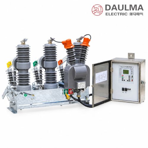
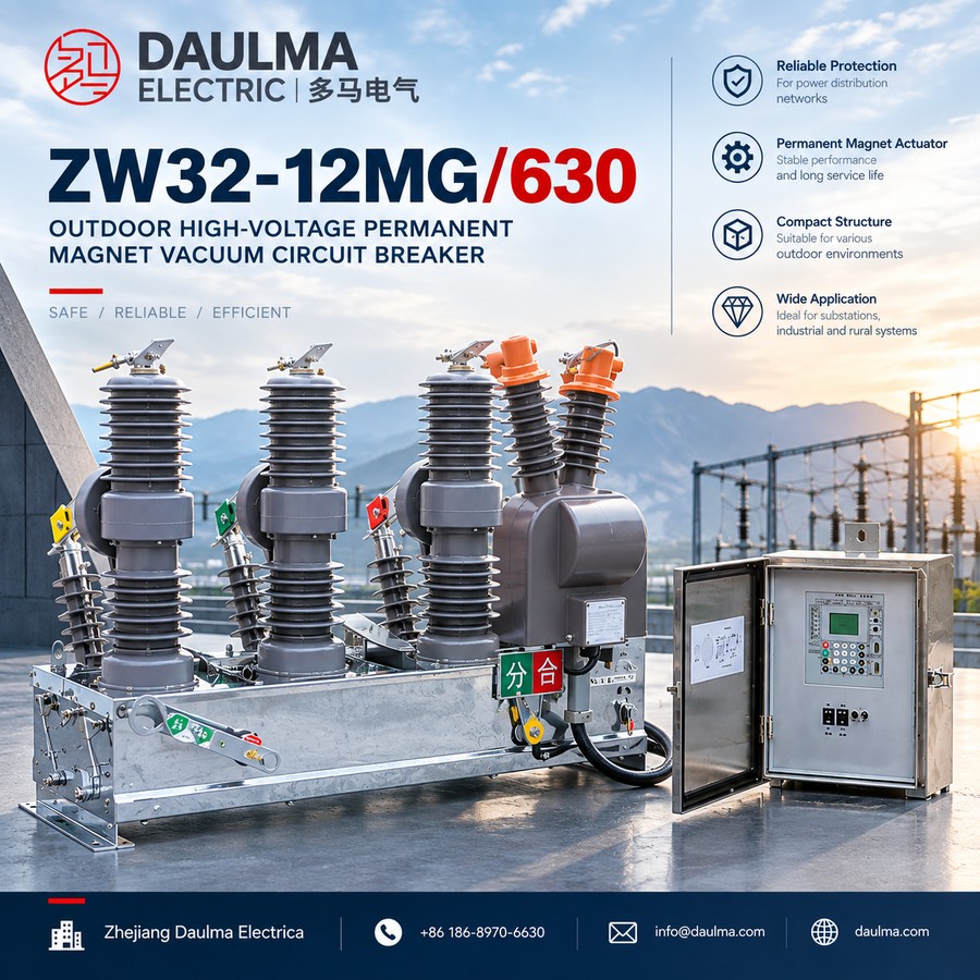
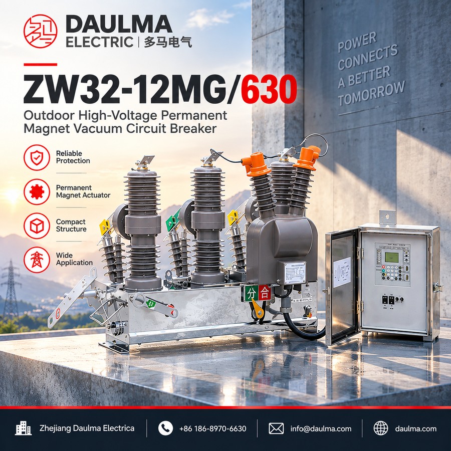
The ZW32-12MG series outdoor permanent magnet vacuum circuit breaker is a three-phase AC 50Hz, 12kV outdoor power distribution equipment designed for switching, making and breaking load current, overload current and short-circuit current in electrical power systems. It is particularly suitable for frequent operation applications in substations, industrial and mining enterprise distribution systems, and rural power grid networks.
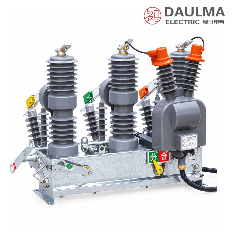
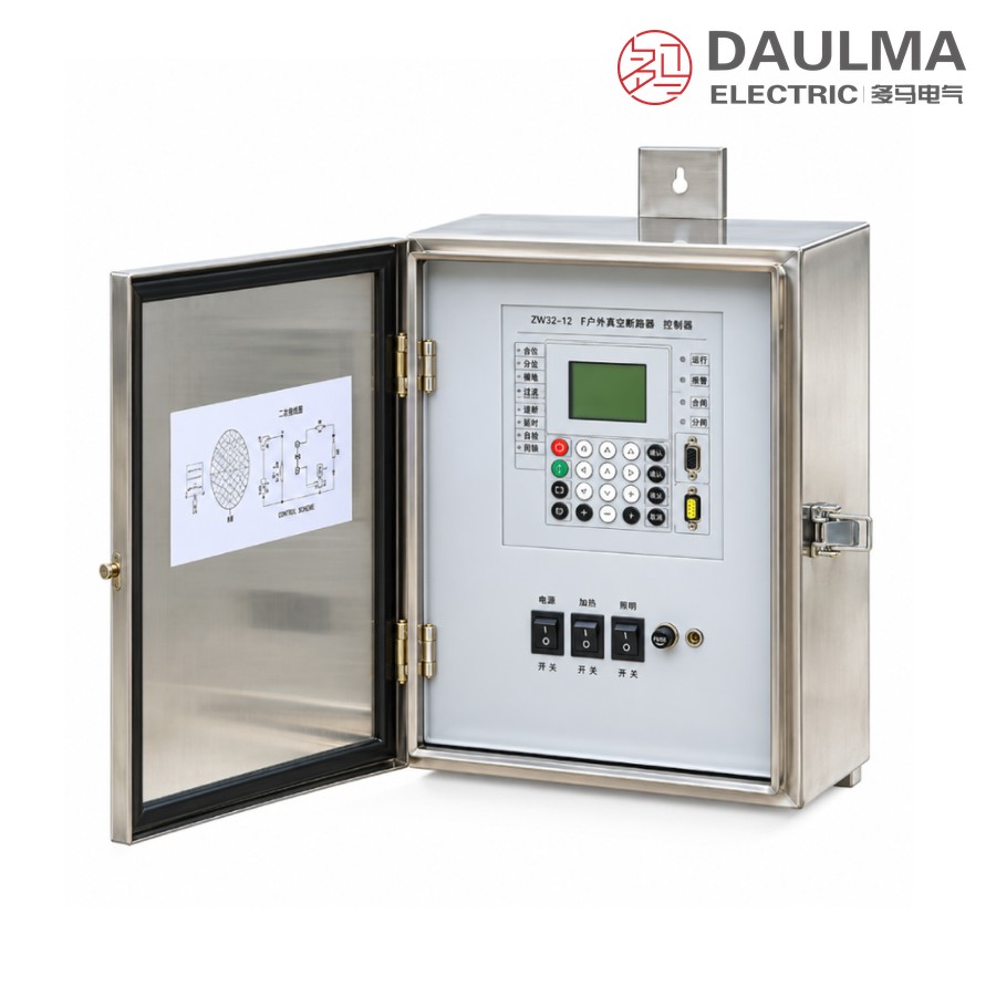
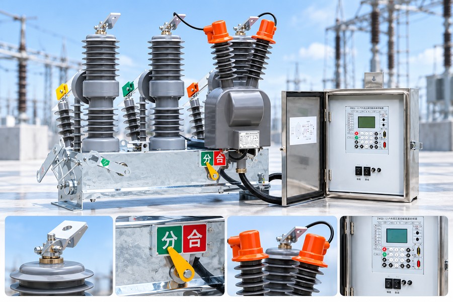
This circuit breaker employs a permanent magnet operating mechanism in which permanent magnets provide the holding force, keeping the contacts reliably in the open or closed position without continuous power consumption. The reduced mechanical parts count and shortened transmission chain greatly enhance operational reliability and mechanical life. The integrated isolating switch (G) provides a visible break point for maintenance safety. When paired with a controller, the unit forms a recloser capable of remote signalling, measurement, control and protection (the “four remote” functions) for distribution automation.
Model Designation
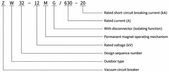
- ZW – Outdoor vacuum circuit breaker
- 32 – Design sequence number
- 12 – Rated voltage (kV)
- M – Permanent magnet operating mechanism
- G – With isolating switch (disconnector)
- 630 – Rated current (A)
- 20 – Rated short-circuit breaking current (kA)
Construction
The ZW32-12MG comprises three main functional assemblies: (1) the interrupter and permanent magnet mechanism module – each pole contains a vacuum interrupter enclosed in a solid dielectric epoxy resin bushing, driven by a direct-acting permanent magnet mechanism with minimal moving parts for high reliability and maintenance-free operation; (2) the isolating switch assembly – a three-phase ganged disconnector mounted above the breaker poles, providing a visible air gap break point for safe maintenance isolation, operated manually or electrically via linkages; (3) the control and wiring enclosure – a weatherproof stainless-steel or galvanised housing at the base containing the permanent magnet coil driver, overcurrent trip unit (5A, ±10% accuracy), auxiliary switches, and a standard multi-core connector for external controller attachment. The entire assembly is hot-dip galvanised for corrosion resistance in outdoor environments and supports both single-pole and double-pole (H-frame) pole mounting configurations.
Technical Parameters
Rated Operating Conditions
| No. | Item | Unit | Parameter |
|---|---|---|---|
| 1 | Rated voltage | kV | 12 |
| 2 | Rated frequency | Hz | 50 |
| 3 | Rated current | A | 630 |
| 4 | Rated short-circuit breaking current | kA | 12.5 / 16 / 20 |
| 5 | Rated short-circuit making current (peak) | kA | 31.5 / 40 / 50 |
| 6 | Rated peak withstand current | kA | 31.5 / 40 / 50 |
| 7 | Rated short-time withstand current (4 s) | kA | 20 |
| 8 | Rated operating sequence | – | O–0.3s–CO–180s–CO |
| 9 | Closing time / Opening time | ms | 25~50 / 15~50 |
| 10 | Rated short-circuit breaking times | ops | 30 |
| 11 | Mechanical life | ops | 10,000 |
| 12 | Control & auxiliary circuit 1-min power-frequency withstand | V | 2000 |
| 13 | Rated operating voltage (control & auxiliary) | V | DC220 / AC220 |
| 14 | Overcurrent trip unit – rated current | A | 5 |
| 15 | Overcurrent trip unit – accuracy | % | ±10 |
Insulation Level
| Item | To Ground / Phase | Across Open Contact |
|---|---|---|
| 1-min power-frequency withstand voltage (dry) | 42 kV | 48 kV |
| 1-min power-frequency withstand voltage (wet) | 34 kV | – |
| Lightning impulse withstand voltage (peak) | 75 kV | 85 kV |
Service Conditions
- Ambient temperature: −45 °C to +40 °C
- Altitude: ≤ 3000 m (higher altitude raises insulation level accordingly)
- Wind speed: ≤ 34 m/s
- Air pollution degree: ≤ Grade IV
- Site free from fire, explosion, chemical corrosion and violent vibration
Installation & Wiring
Installation Diagram
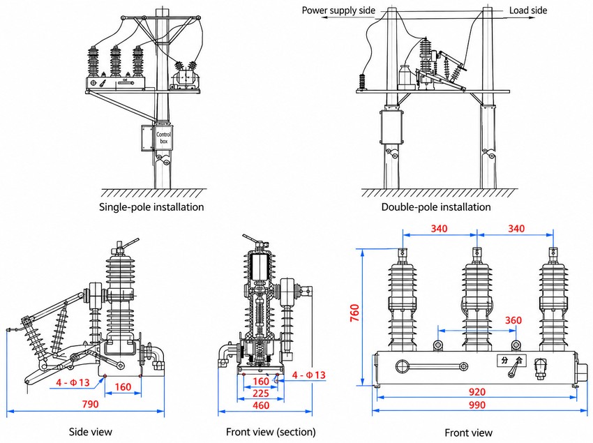
The ZW32-12MG is designed for outdoor pole-mounted installation on either a single pole or a double-pole (H-frame) configuration, as shown in the outline drawing. The permanent magnet mechanism requires no spring charging motor, simplifying wiring to the controller. The integrated isolating switch is accessible from below for manual or electrically-operated ganged switching. Adequate clearance must be maintained around the unit for safe switching and maintenance. All primary and secondary connections must comply with local utility standards.
Outline Dimensions
| Dimension | Value |
|---|---|
| Total height | 760 mm |
| Total width (incl. bushings) | 990 mm |
| Base / frame width | 920 mm |
| Phase spacing (adjacent poles) | 340 mm |
| Overall depth (side view) | 790 mm |
| Mounting hole span (W × D) | 460 × 225 mm |
| Bushing flange width | 160 mm |
| Insulator mounting span | 360 mm |
| Pole-mounting bolt holes | 4 × Φ13 mm |
Selection & FAQs
Selection & Ordering Guide
When specifying the ZW32-12MG, confirm: rated current (630 A standard), breaking capacity tier (12.5 / 16 / 20 kA matching your system fault level), control voltage (DC220 or AC220), isolating switch operation mode (manual S or electric D), and whether a matching controller/recloser relay is required for four-remote automation.
FAQ
- What is the advantage of a permanent magnet mechanism over a spring mechanism?
- The permanent magnet mechanism uses rare-earth magnets to hold the contacts in position without continuous power, eliminating the spring charging motor and reducing moving parts by approximately 60%. This results in higher reliability (>10,000 operations), lower maintenance, faster operating times, and reduced acoustic noise.
- Can the ZW32-12MG be installed on a single pole?
- Yes. The unit supports both single-pole (V-frame) and double-pole (H-frame) mounting. The single-pole configuration uses a cantilever bracket; the double-pole configuration provides additional mechanical stability for high-wind or ice-prone regions.
- What controller is recommended for four-remote functionality?
- The ZW32-12MG is compatible with standard Feeder Terminal Units (FTU) or distribution line monitoring terminals. Pair with any controller supporting the overcurrent trip unit (5A CT input, ±10%) and the auxiliary switch wiring harness provided with the breaker.
- How does the isolating switch (G) differ from the breaker function?
- The isolating switch provides a visible air insulation break point for maintenance safety but is NOT rated for interrupting load or fault current. It must only be operated after the breaker has opened. The breaker interrupts current via the vacuum interrupters.
- What is the expected service life?
- Mechanical life is rated at 10,000 operations. Electrical life at rated current exceeds 2,000 operations. At rated short-circuit breaking current, the vacuum interrupters are rated for 30 operations before replacement. The permanent magnets are designed for the full service life (>20 years) with no degradation under normal conditions.
- Can this breaker operate in extreme cold?
- Yes. The ZW32-12MG is rated for ambient temperatures down to −45 °C, making it suitable for cold-climate installations where conventional spring mechanisms may suffer from lubricant thickening. The solid dielectric insulation and sealed permanent magnet assembly perform reliably at low temperatures.