Overview
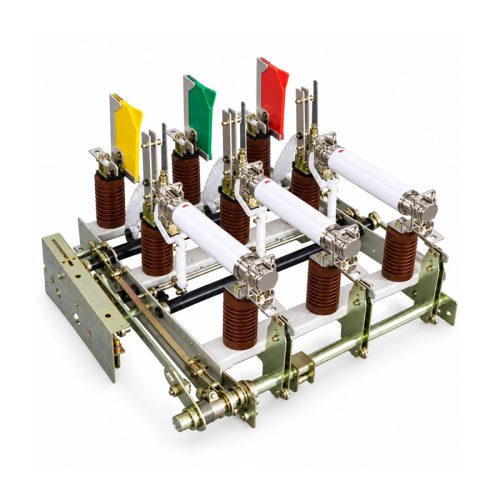
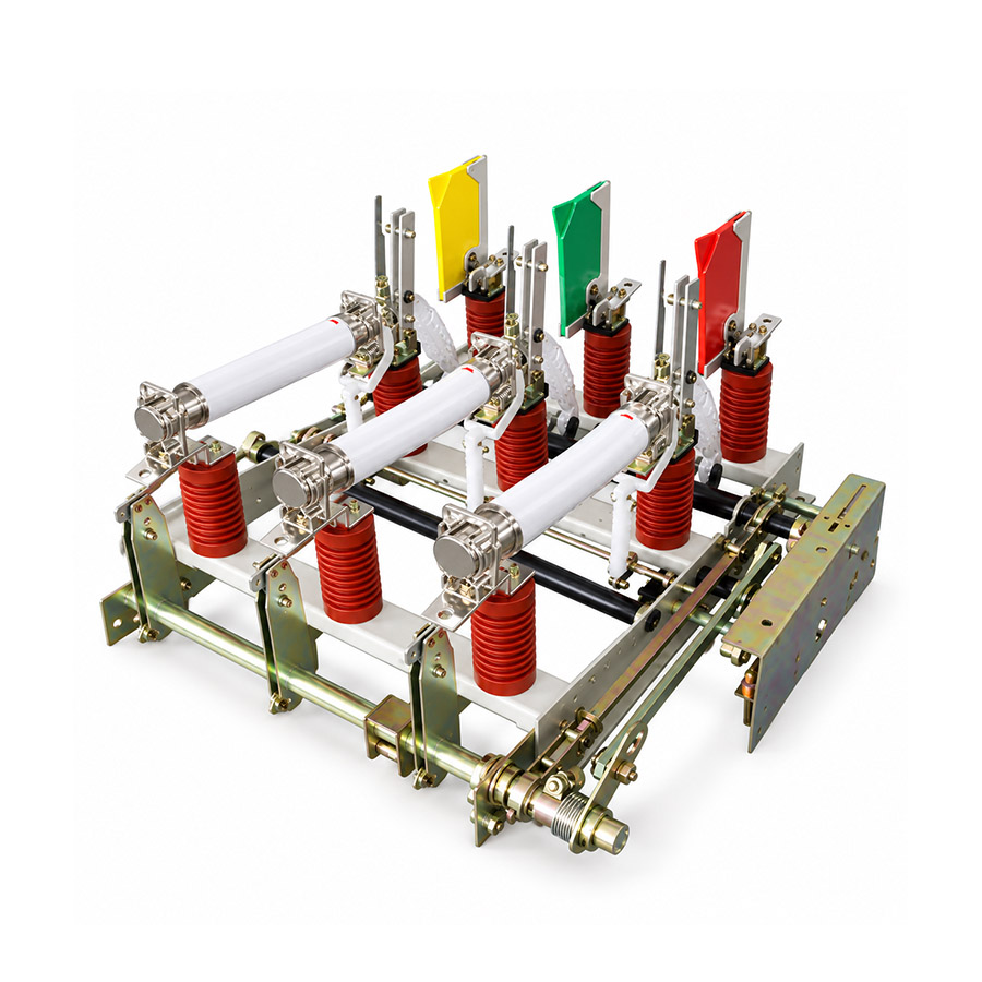
The FN5-12 (RDL) indoor high-voltage load break switch is engineered for dependable performance in 10kV ring networks, distribution boxes, and substations. It complies with IEC 420 and the 1990 edition of “High-Voltage Load Break Switch and Load Break Switchgear” standards, supporting three operational positions: closed, open, and earthed.
Built for AC 50Hz, 12kV systems, this switch reliably breaks rated load currents and closes onto short-circuit currents. When used with a fuse, it provides effective short-circuit fault interruption to safeguard downstream equipment.

Key Ratings Snapshot
| Parameter | Value |
|---|---|
| Rated Voltage | 12 kV |
| Rated Frequency | 50 Hz |
| Rated Current | 630 A |
| Rated Load Breaking Current | 630 A |
| Rated Transfer Current | 1.3 kA |
| Rated Short-Time Withstand Current | 20 kA |
| Rated Peak Withstand Current | 50 kA |
| Mechanical Life | 2000 cycles |
| Rated Short-Circuit Breaking Current | 10 A |
| 5% Rated Load Breaking Current | 31.5 A |
Model Designation
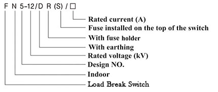
The type designation FN5-12 (RDL) is decoded as follows:
F: Load Break Switch
N: Indoor Application
5: Design Series Number
12: Rated Voltage (12 kV)
D: Equipped with Fuse at Top
R: Capable of Load Breaking
L: With Earth (Grounding) Switch
Construction
The FN5-12 (RDL) features a modular internal structure comprising a base frame, insulation supports, arc tube, damping equipment, moving and static contacts, arcing rod, guide plate, interruption mechanism, locking system, operating mechanism, and an integrated earthing switch. Terminal markings follow standard conventions: P1/P2 denote power-side terminals, while S1/S2 indicate load-side terminals. The top-mounted fuse (indicated by ‘D’ in the type code) provides critical short-circuit protection.
Safety Warning: Always de-energize and verify zero voltage before installation, maintenance, or inspection. Ensure proper grounding and adherence to local electrical codes. Do not operate under load unless explicitly rated for load-breaking duty.
Technical Parameters
Service Conditions
- Altitude: Not exceeding 1000 meters.
- Ambient Temperature: Maximum +40 degC, Minimum -25 degC.
- Relative Humidity: Daily average <=95%, monthly average <=90%.
- Environment: Free from conductive dust, corrosive gases, explosive media, and excessive water vapor.
- Mechanical Stress: No continuous or severe vibration or shock.
Technical Data
| Name | Unit | Value |
|---|---|---|
| Rated Voltage | kV | 12 |
| Maximum Operating Voltage | kV | 12 |
| Rated Frequency | Hz | 50 |
| Rated Current | A | 630 |
| Rated Load Breaking Current | A | 630 |
| 5% Rated Load Breaking Current | A | 31.5 |
| Rated Short-Circuit Breaking Current | A | 10 |
| Rated Moving Contact Current | A | 40 |
| Rated Transfer Current | kA | 1.3 |
| Rated Short-Time Withstand Current | kA | 20 |
| Rated Peak Withstand Current | kA | 50 |
| Mechanical Life | Cycle | 2000 |
Installation & Wiring
Installation Diagram
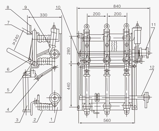
Installation requires secure mounting on a rigid support structure with proper clearance. Ensure alignment of operating mechanism linkages and verify interlock functionality before energization.
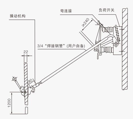
Outline Dimensions
| Component | Description |
|---|---|
| 1 | Base Frame |
| 2 | Insulation |
| 3 | Arc Tube |
| 4 | Damping Equipment |
| 5 | Moving Contact |
| 6 | Arcing Rod |
| 7 | Guide Plate |
| 8 | Static Contact |
| 9 | Interruption Mechanism |
| 10 | Locking Mechanism |
| 11 | Load Break Switch Operating Mechanism |
| 12 | Ground Switch |
Selection & FAQs
Selection Guide
- Confirm a 12kV, 50Hz indoor system and verify the 630A continuous and rated load-breaking current against feeder load and switching duty.
- Select the top-mounted fuse by 12kV class, transformer/load current, minimum breaking current, time-current curve, striker energy and 1.3kA transfer-current coordination.
- Verify 20kA short-time and 50kA peak withstand values against the prospective fault level; these values do not mean the switch itself breaks that current.
- Specify the required closed-open-earthed mechanism, fuse-trip function, door and earthing interlocks, auxiliary contacts and operating-handle arrangement.
- Check ≤1000m altitude, −25°C to +40°C indoor conditions, panel clearances, rigid mounting, linkage alignment, busbar loads and protective grounding.
Frequently Asked Questions
Q1: What is the maximum short-circuit breaking current capacity?
The rated short-circuit breaking current is 10A, with a rated transfer current of 1.3kA. It withstands a short-time current of 20kA. Contact our engineering team for specific fault level calculations.
Q2: Can the FN5-12 switch operate in high humidity environments?
Yes, provided relative humidity does not exceed 95% daily average and 90% monthly average. The environment must remain free from corrosive gases and conductive dust. Verify site conditions before installation.
Q3: Which rated current capacity does the FN5-12 indoor switch provide?
This model offers a standard rated current and load breaking current of 630A. The 5% rated load breaking current is 31.5A. Specify your exact load requirements during the inquiry stage.
Q4: Are routine factory tests performed before shipment?
Routine testing protocols are subject to confirmation based on your specific order requirements. Standard checks typically cover mechanical operations and insulation. Contact our sales team for detailed test certificates.
Q5: How long is the standard delivery time for custom orders?
Standard lead times are subject to confirmation based on order quantity and customization. Typical production takes several weeks after drawing approval. Please contact our procurement department for an exact schedule.
Q6: Why choose the FN5-12 for 12kV ring main units?
It provides reliable load breaking up to 630A and short-circuit making capacity of 50kA peak. The design ensures safe operation in environments free from explosive media. Request a technical proposal for your specific substation layout.