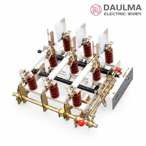
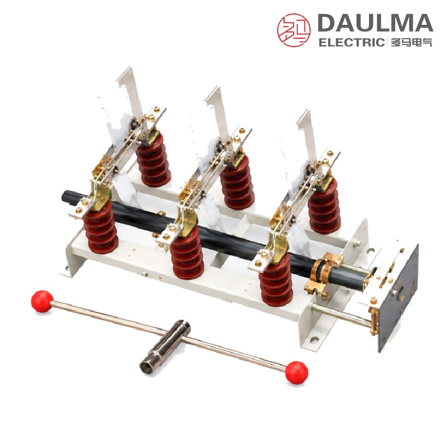
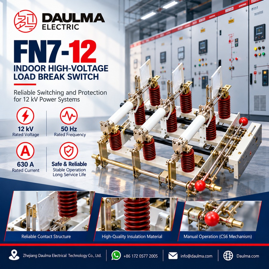
The FN7-12 is an indoor AC high-voltage load break switch of air-insulated construction, designed for use in three-phase 50 Hz power systems rated 12 kV to make and break normal load current and to close on short-circuit current. In FN7-12R form, with current-limiting fuses fitted, the load switch – fuse combination unit interrupts any current up to and including short-circuit current, providing reliable protection for distribution transformers and cable feeders.
The switch is operated by the simple and robust CS6 manual operating mechanism. Nine standard configurations are available, combining incoming- or outgoing-side earthing switches, mechanical interlocking, striker-fuse tripping and a motorised opening device, so that one series with a common base frame covers both line load switching and transformer-feeder protection. Rated currents of 400 A and 630 A provide short-time withstand currents of 12.5 kA and 20 kA (4 s) respectively.
Model Designation
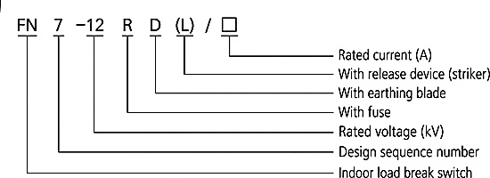
The type is designated FN 7-12 R D (L)/□ and decoded as follows:
- FN — indoor high-voltage load switch
- 7 — design sequence number
- 12 — rated voltage, kV
- R — with fuses (combination unit)
- D — with trip device (striker)
- (L) — with earthing switch
- □ — rated current, A
Example: FN7-12DR/630 denotes a 12 kV fused combination unit with striker trip and a 630 A rated current.
Series Configurations
The series covers nine variants; the option matrix below is reproduced from the datasheet, where △ indicates the feature is fitted. In this table DS/DX denote the earthing switch on the incoming (line) or outgoing side, L the interlocking device, R the fuse, RA the striker fuse and F the motorised opening device.
| Model | DS | DX | L | R | RA | F | Application |
|---|---|---|---|---|---|---|---|
| FN7-12 | — | — | — | — | — | — | Line load switch |
| FN7-12DSL | △ | — | △ | — | — | — | Line load switch |
| FN7-12DXL | — | △ | △ | — | — | — | Line load switch |
| FN7-12R | — | — | — | △ | — | — | Transformer protection |
| FN7-12DSLR | △ | — | △ | △ | — | — | Transformer protection |
| FN7-12DXLR | — | △ | △ | △ | — | — | Transformer protection |
| FN7-12RAF | — | — | — | — | △ | △ | Transformer protection |
| FN7-12DSLRAF | △ | — | △ | — | △ | △ | Transformer protection |
| FN7-12DXLRAF | — | △ | △ | — | △ | △ | Transformer protection |
Construction and Operating Mechanism
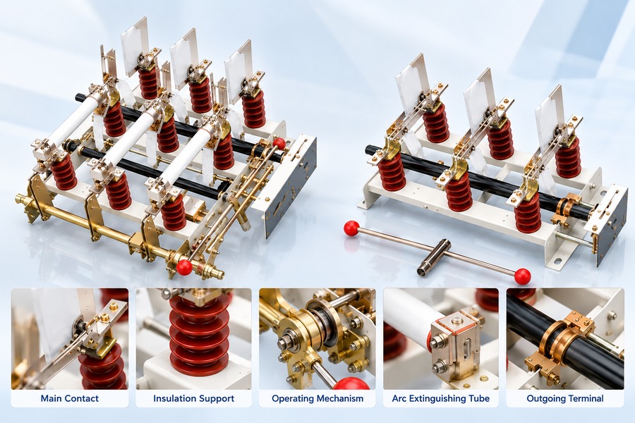
- Air-insulated open construction. Live parts, blades and current-limiting fuses are mounted on a common steel frame with a visible isolating gap rated 48 kV (1 min power frequency) and 85 kV lightning impulse across the gap, allowing the unit to serve as both switch and isolator within its rating.
- CS6 manual mechanism. The on-frame CS6 mechanism gives simple, reliable make and break operation with low maintenance; the operating handle requires about 1200 mm of clearance as shown on the outline drawings.
- Fuse tripping and interlocking. On striker-fuse (RA) versions the fuse striker opens the corresponding switch pole after a fault; the interlocking device (L) enforces the correct operating sequence between switch and earthing switch, and the motorised opening device (F) permits remote or automatic tripping.
Technical Parameters
Service Conditions
- Ambient temperature: upper limit +40℃, lower limit -25℃
- Altitude: not above 1000 m
- Relative humidity: daily average ≤ 95%, monthly average ≤ 90%
- Environment: free from corrosive or flammable gases, vapour or obvious pollution
- Vibration: no frequent violent vibration
Main Technical Parameters
The FN7-12 is offered in two rated-current classes; the two columns below compare the 400 A and 630 A versions.
| No. | Item | Unit | 400 A
version |
630 A
version |
|---|---|---|---|---|
| 1 | Rated voltage | kV | 12 | 12 |
| 2 | Rated frequency | Hz | 50 | 50 |
| 3 | Rated current | A | 400 | 630 |
| 4 | 1 min power-frequency withstand voltage (phase-to-phase / to earth) | kV | 42 | 42 |
| 5 | 1 min power-frequency withstand voltage (isolating gap) | kV | 48 | 48 |
| 6 | Lightning impulse withstand voltage (phase-to-phase / to earth) | kV | 75 | 75 |
| 7 | Lightning impulse withstand voltage (isolating gap) | kV | 85 | 85 |
| 8 | Rated short-time withstand current (4 s) | kA | 12.5 | 20 |
| 9 | Rated peak withstand current | kA | 31.5 | 50 |
| 10 | Rated short-circuit making current (peak) | kA | 31.5 | 50 |
Installation & Wiring
Installation and Mounting
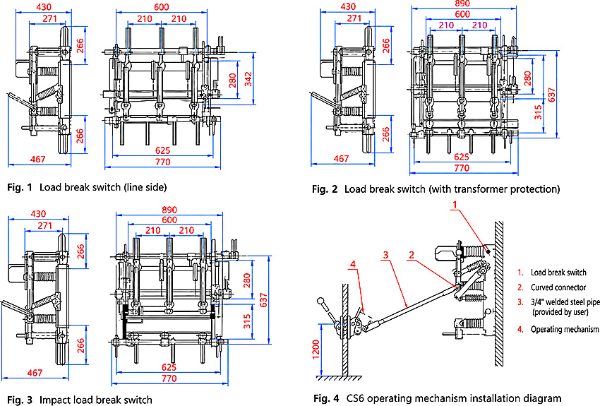
The FN7-12 is a fixed-mounted indoor switch installed on a wall or panel frame, with the steel frame reliably earthed. Connect incoming and outgoing cables to the terminals, fit the fuse cartridges (R / RA versions) and refit the enclosing barrier. The CS6 mechanism uses a 3/4-inch welded steel pipe extension rod (user-supplied) with about 1200 mm clearance (Fig. 4); check the earthing switch and interlocking before commissioning.
Outline and Installation Dimensions
Dimensions below are taken from drawings Fig. 1-4: line-side version, transformer-protection (fused) version, striker-fuse version and CS6 mechanism installation.
| Outline dimension | Value (mm) |
|---|---|
| Base frame overall width (all versions) | 770 |
| Upper structure width, line-side version (Fig. 1) | 600 |
| Upper structure width, fused versions (Fig. 2-3) | 890 |
| Base mounting hole span | 625 |
| Phase spacing | 210 + 210 |
| Depth, side view (upper section / overall) | 430 / 467 |
| Overall height, line-side version (Fig. 1) | 342 |
| Overall height, fused versions (Fig. 2-3) | 637 |
| Support insulator section height (upper + lower) | 266 + 266 |
| Operating mechanism installation height (Fig. 4) | 1200 |
Applications
- 12 kV indoor distribution stations, ring-main units and terminal substations for line load switching
- Protection and control of distribution transformers by load switch – fuse combination units (FN7-12R / RA versions)
- Sectionalising and supply-switching of cable and overhead feeders without a dedicated circuit breaker
Selection & FAQs
Selection Guide
- Rated current class. Choose 400 A (12.5 kA / 4 s) or 630 A (20 kA / 4 s) against the continuous load current and the system short-circuit level.
- Duty. Basic FN7-12 and DSL / DXL versions serve line load switching; R, SLR and RAF-type versions add fuses for transformer protection.
- Earthing switch. Select DS (incoming side), DX (outgoing side) or no earthing switch according to the feeding arrangement and maintenance practice.
- Trip and interlocking. Add L interlocking for enforced operating sequence, RA striker trip for automatic fuse-initiated opening, and F motorised opening for remote or automatic tripping schemes.
- Service conditions. Confirm the indoor site within -25℃ to +40℃, altitude ≤ 1000 m, humidity daily ≤ 95% / monthly ≤ 90%; otherwise refer to the technical agreement.
- Compare neighbouring designs. For vacuum dielectric load switching see FZN25-12D; for other options see HV Load Break Switches.
FAQs
Q1: What does the type designation FN7-12R D(L)/□ mean?
FN denotes an indoor high-voltage load switch, 7 the design sequence and 12 the rated voltage in kV; R adds current-limiting fuses (combination unit), D a striker trip device, (L) an earthing switch, and the final box the rated current in amperes. FN7-12DR/630 is therefore a 630 A fused, striker-tripped combination unit.
Q2: What is the difference between FN7-12 and FN7-12R?
The FN7-12 is the load switch alone, rated to make and break load current and to close on short-circuit current. The FN7-12R carries current-limiting fuses as a combination unit, so the set can interrupt any current up to and including short-circuit current, which is what makes it suitable for transformer protection.
Q3: How do the fuse and the load switch share the duty during a fault?
Load currents are switched by the break switch itself. On a short circuit the current-limiting fuse operates first and clears the fault; on striker-fuse (RA) versions the fuse striker then opens the corresponding switch pole so that the faulted phase is also isolated by the switch.
Q4: What are the insulation levels and the two current ratings?
For the 12 kV class the 1 min power-frequency withstand is 42 kV phase-to-phase and to earth and 48 kV across the isolating gap; the lightning impulse withstand is 75 kV and 85 kV respectively. The 400 A version carries 12.5 kA (4 s) short-time withstand, the 630 A version 20 kA.
Q5: What are the service conditions?
Indoor installation with ambient temperature between -25℃ and +40℃, altitude not above 1000 m, relative humidity daily average ≤ 95% and monthly average ≤ 90%, free from corrosive or flammable gas, vapour or obvious pollution, and without frequent violent vibration.
Q6: What data should I provide when ordering?
Please state the model and configuration (DS / DX / L / R / RA / F options), rated voltage, rated current (400 or 630 A), short-time withstand requirement, fuse type and rating for combination units, control voltage for the motorised opening device, quantity, and any special service conditions.