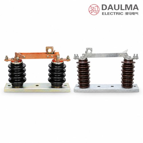
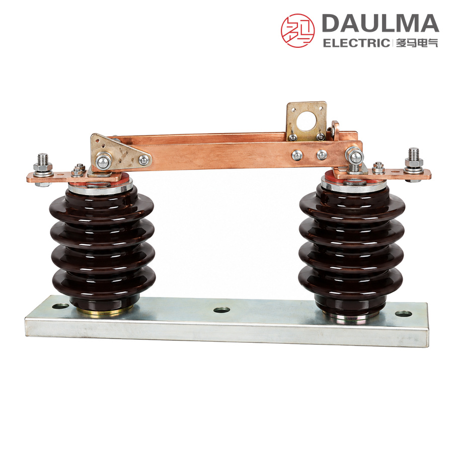
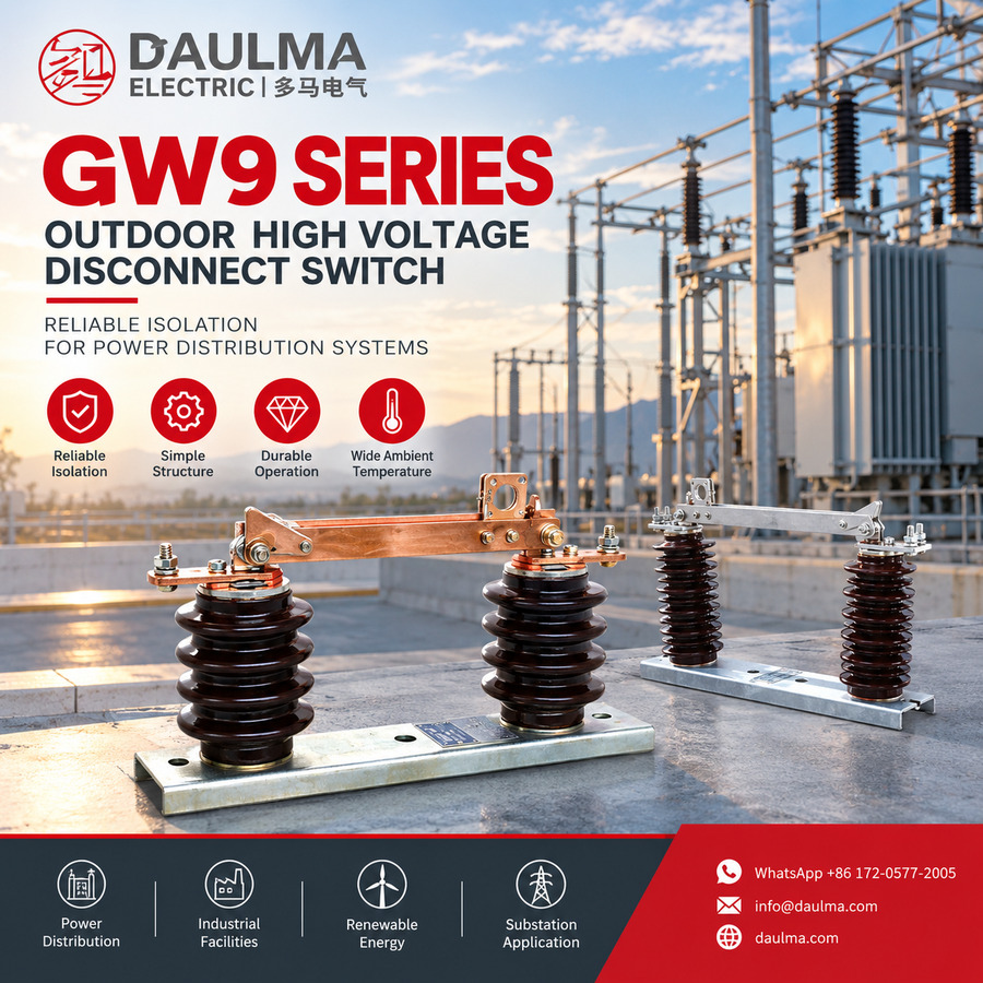
The GW9 is a single-pole outdoor high-voltage disconnector of AC 50 Hz for networks with rated voltages of 10 kV, 15 kV and 24 kV. It is used to open and close high-voltage lines under no load and to isolate the live parts of a circuit from busbars, circuit breakers and other equipment under maintenance, and it may also make and break small capacitive or inductive currents.
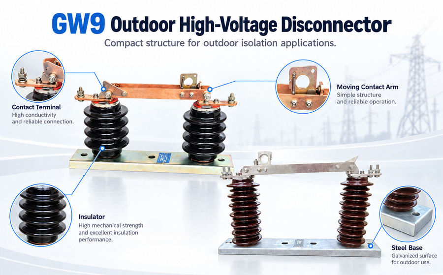
Each pole is an independent unit: two porcelain post insulators stand on a common steel base and carry the moving knife and the static contact with its terminal above them, so that three poles set side by side form the three-phase isolating switch. The series is designed to GB 1985, IEC 60129 and GB/T 11022, and a wall-bushing version and a pollution-proof version are available.
Model Designation
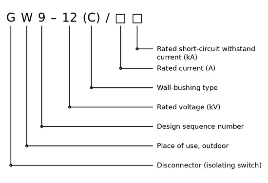
The type is designated G W9-12 (C)/□□ and decoded as follows:
- G — disconnector
- W — place of use, outdoor
- 9 — design sequence number
- 12 — rated voltage, kV
- (C) — wall-bushing type (omitted for the standard type)
- □ — rated current, A
- □ — rated short-circuit withstand current, kA
Construction and Operation
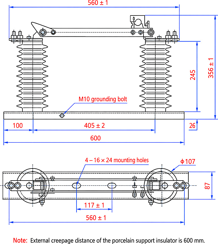
- Single-pole unit. The base is a 600 mm long, 87 mm wide steel frame with four 16 × 24 mm mounting holes and an M10 earthing bolt, so each pole can be transported, installed and maintained separately.
- Insulation. Two porcelain post insulators on 405 ± 2 mm centres, each with an external creepage distance of 600 mm, support the live parts 245 mm above the base and give a total height of 356 ± 1 mm.
- Contact system. The knife rotates onto the static contacts at the terminal blocks, and the open position provides the insulating gap that makes the isolated circuit visibly safe for personnel.
- No-load duty. The disconnector has no breaking capacity for load or short-circuit current; it switches no-load lines and small capacitive or inductive currents and is used in combination with a circuit breaker.
- Wall-bushing type (C). On request the pole is supplied as a wall-bushing version for penetration through a wall or panel partition.
- Pollution-proof version. Creepage distances of 300 mm (10 kV) and 380 mm (15 kV) are tabulated for the standard insulation; the pollution-proof version is intended for heavily polluted areas.
- Long service life. Mechanical life is 2000 operating cycles for every rated voltage group.
Technical Parameters
Rated Parameters
Reproduced from the catalogue table: the three rated-voltage groups of 10, 15 and 24 kV each cover two rated-current steps.
| No. | Item | Unit | Parameters | ||||||||
|---|---|---|---|---|---|---|---|---|---|---|---|
| 1 | Rated voltage | kV | 10 | 15 | 24 | ||||||
| 2 | Rated operational voltage | kV | 12 | 17.5 | — | ||||||
| 3 | Rated insulation level | 1 min power-frequency withstand voltage (r.m.s.) | To earth | kV | 42 | 55 | 65 | ||||
| Across the break | kV | 48 | 65 | 79 | |||||||
| Lightning impulse withstand voltage (peak) | To earth | kV | 75 | 105 | 125 | ||||||
| Across the break | kV | 85 | 120 | 145 | |||||||
| 4 | Rated frequency | Hz | 50 | ||||||||
| 5 | Rated current | A | 200 | 400 | 630 | 1250 | 400 | 630 | |||
| 6 | 4 s short-time withstand current | kA | 6.3 | 12.5 | 20 | 31.5 | 16 | 20 | |||
| 7 | Rated peak withstand current | kA | 16 | 31.5 | 50 | 80 | 40 | 50 | |||
| 8 | Creepage distance | mm | 300 | 380 | — | ||||||
| 9 | Mechanical life | operations | 2000 | 2000 | 2000 | ||||||
Normal Service Conditions
- Altitude: not exceeding 1000 m
- Ambient air temperature: upper limit +40℃, lower limit −30℃ in general areas and −40℃ in cold areas
- Wind pressure: not exceeding 700 Pa, equivalent to a wind speed of 34 m/s
- Vibration: no frequent or severe vibration at the installation site
- Standard type: installation site free from gases, vapours, chemical deposits, salt mist, dust or other explosive or corrosive substances that seriously affect the insulation and conductivity of the disconnector
- Pollution-proof type: suitable for heavily polluted areas, but without substances that may cause fire or explosion
Design Standards
- GB 1985 — High-voltage AC disconnectors and earthing switches
- IEC 60129 — AC disconnectors and short-circuit making switches
- GB/T 11022 — Common specifications for high-voltage switchgear and controlgear standards
Installation & Wiring
Installation and Mounting
Set the single poles side by side on the supporting structure at the specified phase spacing and fix each base through the four 16 × 24 mm holes on 560 ± 1 mm centres; connect the M10 earthing bolt reliably. Join the incoming and outgoing conductors to the terminal blocks, then check that the knife closes fully home and that the open position gives the tabulated insulating gap.
Outline and Installation Dimensions
Dimensions of one pole (mm) are taken from the outline drawing above.
| Outline dimension | Value (mm) |
|---|---|
| Base frame length | 600 |
| Base frame width | 87 |
| Base plate thickness | 26 |
| Distance from base end to insulator axis | 100 |
| Supporting insulator centres | 405 ± 2 |
| Mounting hole centres | 560 ± 1 |
| Mounting holes | 4 × 16 × 24 |
| Terminal height above base | 245 |
| Total height | 356 ± 1 |
| Insulator flange diameter | 107 |
| Earthing bolt | M10 |
| Post insulator external creepage distance | 600 |
Applications
- Isolation of outdoor 10 kV, 15 kV and 24 kV lines, busbars and circuit breakers during maintenance
- No-load switching operations in substation, industrial and distribution installations
- Making and breaking of small capacitive or inductive currents in the associated circuit
- Wall-bushing (C) version for penetration through walls and panel partitions
- Pollution-proof version for coastal, salt-mist and heavily polluted industrial areas
Selection & FAQs
Selection Guide
- Match the rated voltage group — 10, 15 or 24 kV — to the network, and check the insulation levels against the site.
- Select the rated current from the tabulated steps and verify the 4 s and peak withstand currents.
- Choose the standard pole or the wall-bushing (C) version for the supporting structure.
- Order the pollution-proof version for heavily polluted or coastal installation sites.
- Confirm altitude, temperature range and wind pressure against the service conditions.
Frequently Asked Questions
Q1: What does the type designation GW9-12 (C)/□□ mean?
G is the disconnector and W the outdoor place of use; 9 is the design sequence number and 12 the rated voltage in kV. C marks the wall-bushing type, and the two final fields give the rated current in A and the rated short-circuit withstand current in kA.
Q2: Can the GW9 disconnector interrupt load or short-circuit current?
No. It opens and closes lines under no load and makes or breaks only small capacitive or inductive currents. Load and short-circuit currents are interrupted by the associated circuit breaker, and the two devices must be interlocked so that the disconnector cannot be operated under load.
Q3: Which rated voltages and currents are available?
Three rated-voltage groups of 10, 15 and 24 kV are offered, each with two rated-current steps from 200 A to 1250 A. The 4 s short-time withstand current ranges from 6.3 kA to 31.5 kA and the rated peak withstand current from 16 kA to 80 kA, as tabulated.
Q4: What is the wall-bushing (C) version used for?
It is the same single-pole disconnector supplied for penetration through a wall or a panel partition, so the live parts pass through the barrier while the base remains fixed to the structure; it saves a separate mounting frame where the switchgear is separated by a wall.
Q5: What are the service conditions?
Altitude not exceeding 1000 m, ambient air temperature with an upper limit of +40℃ and a lower limit of −30℃ in general areas or −40℃ in cold areas, wind pressure up to 700 Pa (34 m/s), and no frequent or severe vibration at the site.
Q6: Which standards apply, and what data should I provide when ordering?
The series complies with GB 1985, IEC 60129 and GB/T 11022. When ordering, state the rated voltage group, rated current, rated short-circuit withstand current, standard or wall-bushing (C) type, standard or pollution-proof insulators and the quantity of poles; see also our GW-15 outdoor disconnector for higher voltage classes and the disconnector range.