Introduction to Combined Transformers and Their Classification
Introduction to Combined Transformers and Their Classification
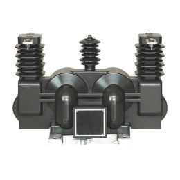
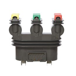
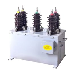
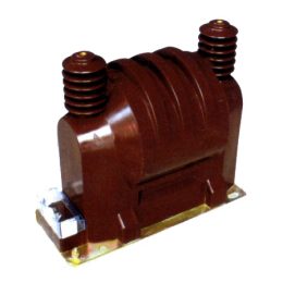
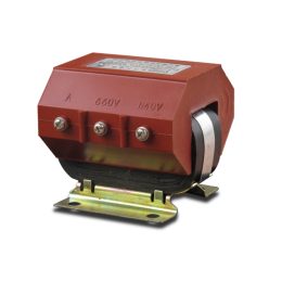
A combined transformer, also known as a composite transformer, is an integrated unit that combines a voltage transformer (VT) and a current transformer (CT). These transformers are often produced together as part of a system for more efficient and space-saving installation. The combined transformer may be used for measurement, protection, and control purposes in power systems.
Current Transformer (CT) Classification
By Purpose
- Measurement Current Transformer (CT):
A measurement CT (or the measurement winding of a current transformer) provides current information from the power grid to measuring or metering devices under normal operating conditions. It ensures accurate current monitoring for metering and load measurement applications. - Protection Current Transformer (CT):
A protection CT (or the protection winding of a current transformer) supplies current information to relay protection devices in the event of a fault in the power grid. This type of CT is critical for detecting abnormal current conditions, enabling the timely triggering of protection mechanisms during fault events.
By Insulation Medium
- Dry-Type Current Transformer:
In dry-type current transformers, the insulation is made from regular insulating materials that are treated with varnish or resin for protection. These transformers are typically used in controlled indoor environments. - Cast Resin Current Transformer:
A cast resin CT is molded using epoxy resin or other resin-based materials. This type of CT offers high mechanical strength and excellent insulation properties, making it ideal for use in harsh environments. - Oil-Filled Current Transformer:
Oil-filled CTs use insulating oil combined with insulating paper. These transformers are often used outdoors and are common in various voltage levels, especially in China, where they are a standard choice for many applications. - Gas-Insulated Current Transformer:
A gas-insulated CT uses a gas, such as SF6, as its primary insulation medium. This type is typically used in high-voltage applications and offers compactness and improved dielectric properties.
By Current Transformation Principle
- Electromagnetic Current Transformer:
The electromagnetic CT operates based on the principle of electromagnetic induction to transform the primary current into a proportional secondary current. This is the most common type of CT and is widely used for voltages up to 220 kV. - Optical Current Transformer (in Development):
This type of CT, still under research, uses optical principles for current transformation. Optical CTs are expected to provide higher accuracy and isolation, offering promising advancements for high-precision applications.
By Installation Type
- Through-Type Current Transformer:
A through-type CT is designed to be mounted by passing the primary conductor (or busbar) through the center of the transformer. These CTs are often used in systems where space and ease of installation are critical. - Post-Type Current Transformer:
Post-type CTs are installed on a flat surface or pole, where the transformer serves as both the current transformer and as a support structure for the primary circuit conductor. These are commonly used in outdoor installations. - Bushing-Type Current Transformer:
A bushing-type CT does not require primary conductors or insulation; instead, it directly fits over an insulated bushing. This type is often used in transformer bushings and other high-voltage equipment. - Busbar-Type Current Transformer:
A busbar-type CT does not require a primary conductor but instead fits over the busbar itself, allowing for easy installation and monitoring of the current without direct access to the primary conductor.
By Principle
- Electromagnetic Induction Type:
This type of CT operates using electromagnetic induction to transform current and is the most common for use in voltage levels up to 220 kV. - Capacitive Voltage Divider Type:
Capacitive voltage divider CTs are typically used in systems with voltages of 110 kV and above, especially in ultra-high voltage (UHV) applications from 330 kV to 765 kV. These CTs use a capacitive divider to step down the high voltage for measurement and protection purposes.
Voltage Transformer (VT) Classification
Voltage transformers are divided into two main categories based on their purpose:
- Measurement Voltage Transformers:
These transformers are primarily used for voltage measurement in power systems. The main technical requirement for measurement VTs is to provide high accuracy to ensure proper voltage monitoring. - Protection Voltage Transformers:
Protection VTs serve to detect voltage faults in the system, triggering protection devices such as circuit breakers or relay systems. These transformers may have special features, including a third winding or provisions for zero-sequence flux in the core, to meet specific protection requirements.
Conclusion
Combined transformers, which integrate both current and voltage transformers into a single unit, offer a compact and efficient solution for power system measurement, protection, and control. Understanding the different classifications of current and voltage transformers—based on their purpose, insulation medium, installation type, and operating principle—allows engineers to select the most appropriate equipment for each application. This comprehensive classification ensures that the right type of transformer is used to meet the specific demands of both regular operation and protection in high-voltage systems.
- Analysis of the Impact of Current Transformer Faults on Energy Meter Accuracy
- Introduction to Combined Transformers and Their Classification
- Single-Phase Voltage Transformers Role, Function, and Importance in Power Systems
- Causes and Solutions for False Fault Alarms in Zero-Sequence Current Transformers
- Troubleshooting Techniques for Burnt Voltage Transformers
- Instrument Transformer Fault Handling: A Technical Guide
