Overview
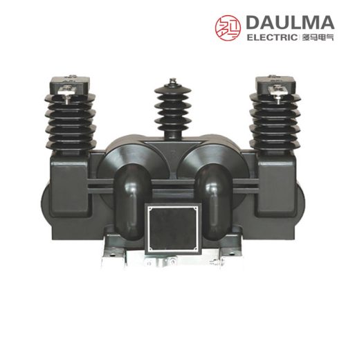
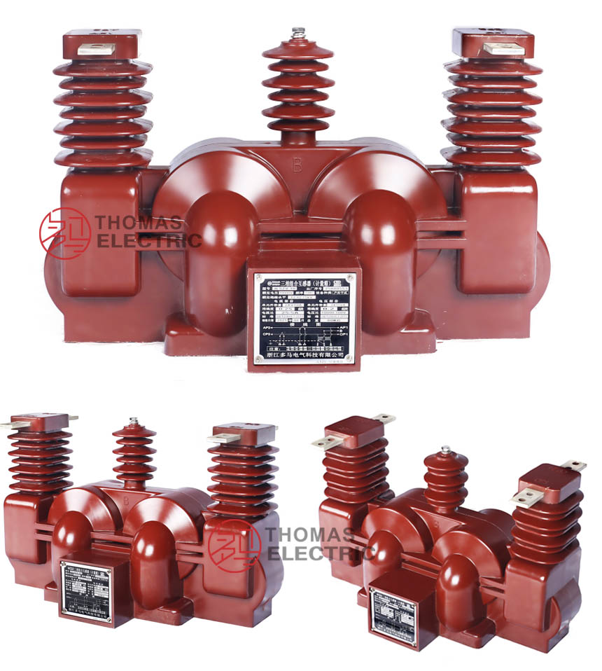
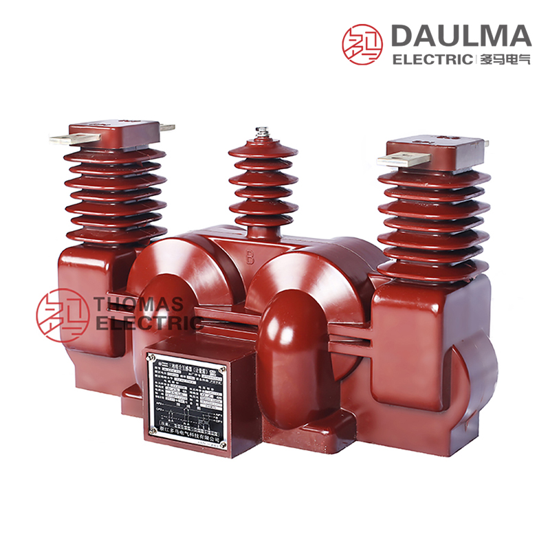
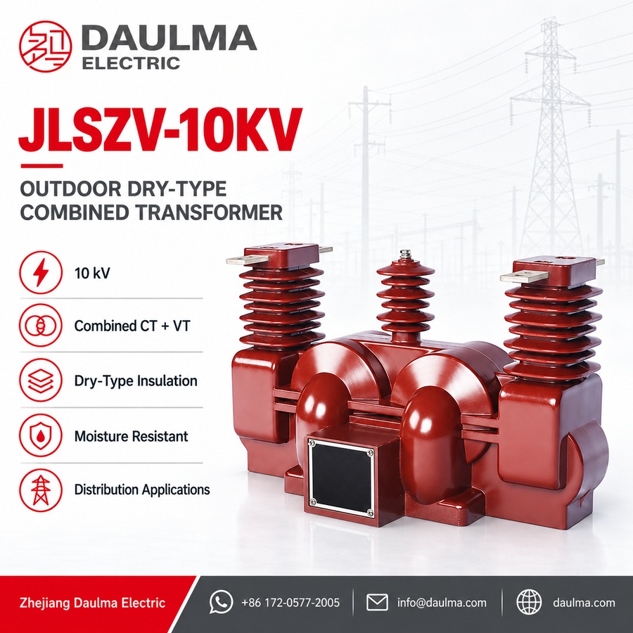
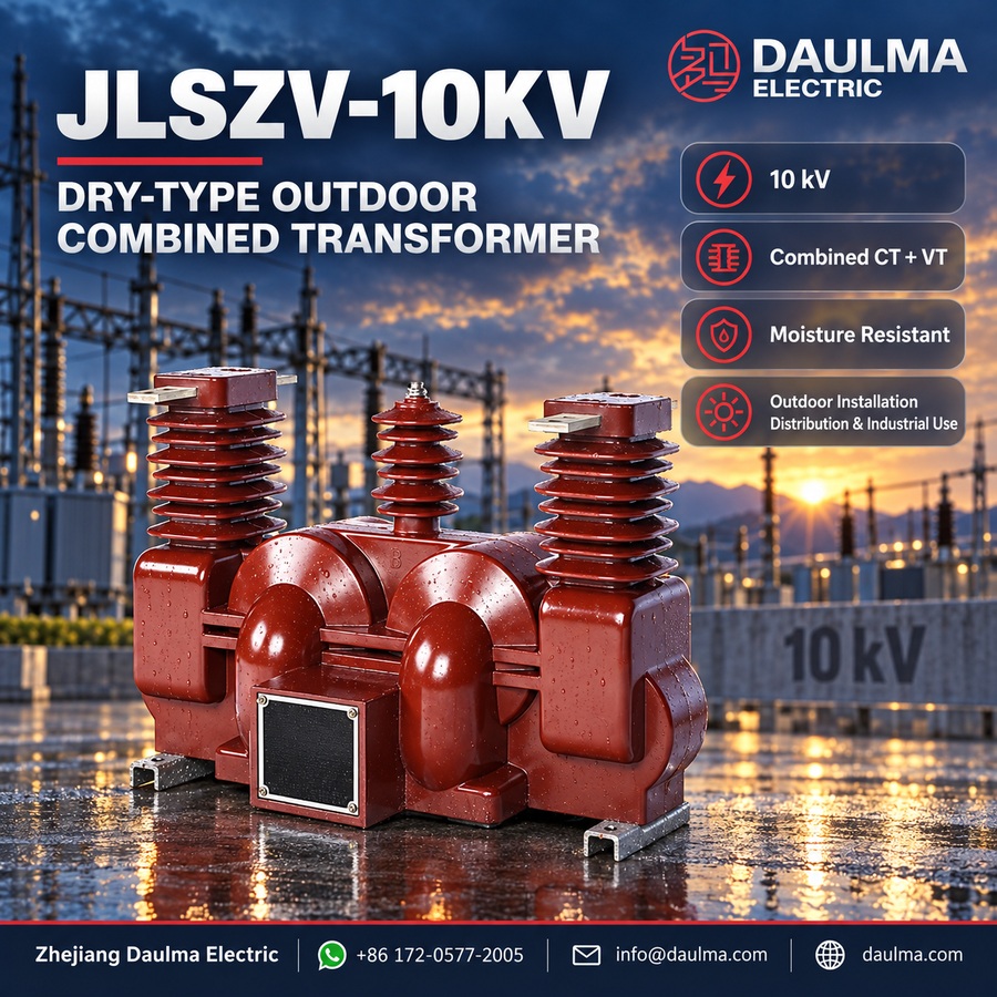
The JLSZV-10kV three-phase outdoor combined instrument transformer integrates dry-type voltage transformers (VTs) in V/V connection with current transformers (CTs) for precise metering and monitoring in 6-10 kV AC distribution networks. Designed for outdoor use, it delivers galvanically isolated secondary signals proportional to primary voltage and current, supporting revenue-grade energy measurement and system protection.
This compact, maintenance-free unit replaces traditional oil-immersed transformers in grid modernization projects, offering superior pollution resistance, environmental safety, and long-term stability without oil handling or leakage risks.
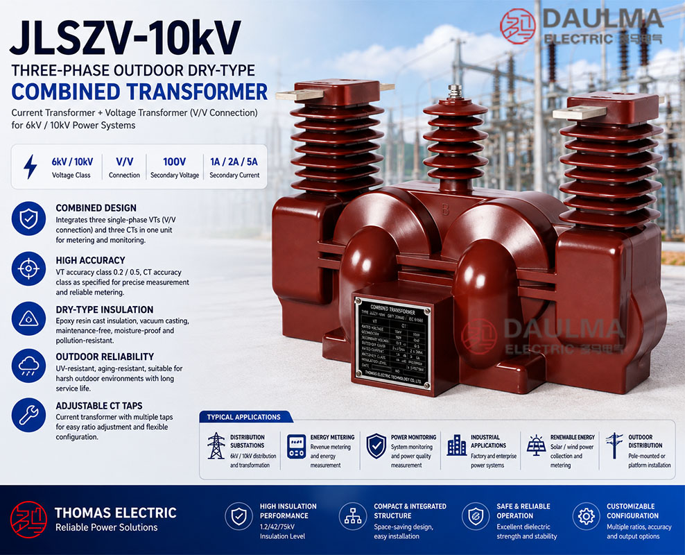
Key Ratings Snapshot
| Parameter | Value |
|---|---|
| System voltage class | 6 kV / 10 kV |
| Rated frequency | 50 Hz (60 Hz on request) |
| VT configuration | V/V connection (three single-phase units) |
| VT secondary voltage | 100 V |
| VT accuracy class | 0.2 / 0.5 |
| VT rated output | 2 x 15 VA (0.2) / 2 x 30 VA (0.5) |
| CT secondary current | 1 A, 2 A, or 5 A |
| Insulation level | 1.2/42/75 kV |
| Creepage distance | 440 mm |
| Insulation material | Epoxy resin cast (vacuum-cast outdoor-grade) |
Model Designation
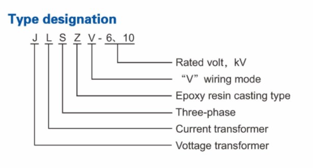
- J: Combined instrument transformer (voltage + current)
- L: Current transformer component
- S: Three-phase configuration
- Z: Outdoor support (pillar/post) type mounting
- V: Voltage transformer component with V/V connection
- 10: Voltage class (kV) â applicable for 6 kV and 10 kV systems
Construction
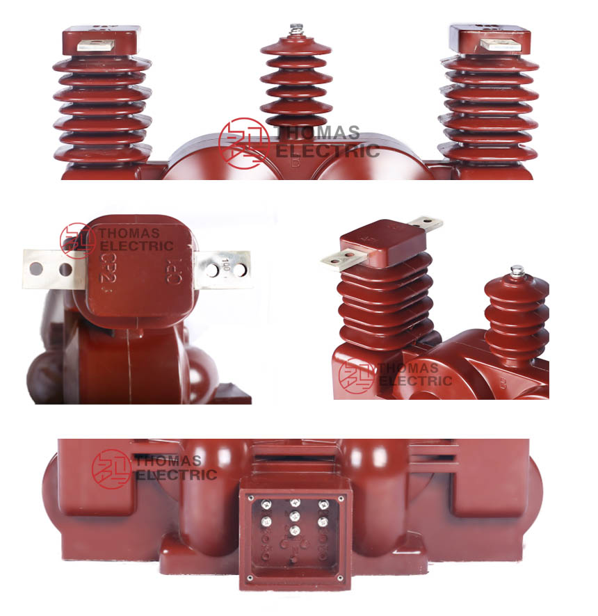
The JLSZV-10kV features fully enclosed epoxy resin vacuum-cast construction, ensuring high mechanical strength, moisture resistance, and pollution resistance for reliable outdoor service. The integrated assembly combines three-phase VTs in V/V configuration with adjustable-tap CTs in a single pole- or ground-mountable housing.
The outdoor-grade epoxy formulation provides UV resistance, weathering resistance, and long-term dielectric stability across varying environmental conditions. This maintenance-free design eliminates oil-related maintenance and environmental hazards, requiring only periodic external cleaning during its service life.
Technical Parameters
Service Conditions
- Installation environment: Outdoor (pollution-resistant epoxy resin construction)
- Altitude: Not exceeding 1000 m above sea level (higher on request)
- Ambient temperature: -25 deg C to +45 deg C
- Relative humidity: Daily average <= 95%, monthly average <= 90% (at +20 deg C)
- Pollution level: Moderate to heavy (creepage distance >= 440 mm)
- Environmental conditions: Resistant to UV, rain, snow, ice, and atmospheric pollution; no explosive atmosphere
Technical Data
| Rated Primary Current Range (A) |
Rated Short-Time Thermal Current (Ith) (kA RMS) |
Rated Dynamic Current (Idyn) (kA peak) |
Rated Secondary Output (VA) |
|---|---|---|---|
| 5 : 10 | 1.0 | 2.5 | 10 |
| 10 : 20 | 1.5 | 3.75 | 10 |
| 15 : 30 | 2.4 | 6.0 | 10 |
| 20 : 40 | 3.0 | 7.5 | 10 |
| 30 : 60 | 4.5 | 11 | 10 |
| 40 : 75 | 8.0 | 20 | 10 |
| 50 : 100 | 9.0 | 22.5 | 10 |
| 75 : 150 | 12 | 30 | 10 |
| 100 : 200 | 16 | 40 | 10 |
| 150 : 300 | 24 | 60 | 10 |
| 200 : 400 | 32 | 80 | 10 |
| 300 : 600 | 60 | 100 | 10 |
| 400 : 800 | 80 | 100 | 10 |
| 500 : 1000 | 80 | 100 | 10 |
Installation & Wiring
Installation Diagram
The JLSZV-10kV combined transformer is designed for secure pole-mounted or ground-mounted installation using designated brackets per project-specific drawings. Primary connections can be made via overhead conductors, cable terminations, or busbars. Ensure adequate clearance for insulation coordination, heat dissipation, and safe maintenance access as per local electrical codes.
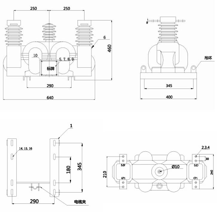
Outline Dimensions
| Dimension | Value (mm) |
|---|---|
| Total height | Project-specific (see dimensional drawing) |
| Base mounting hole pattern | Per installation drawing |
| Phase spacing (A-B-C) | As per system layout |
| Minimum creepage distance | 440 |
Selection & FAQs
Selection Guide
- Specify system voltage (6 kV or 10 kV) and primary current based on feeder load profile.
- Select VT accuracy class (0.2 for high-precision metering, 0.5 for general applications) and verify burden matches connected meters.
- Choose CT secondary current (1 A, 2 A, or 5 A) per local utility standards and ensure burden compatibility.
- Confirm Ith and Idyn ratings align with system fault levels at the installation point.
- For altitudes >1000 m, coastal areas, or severe pollution, request enhanced creepage or derating analysis.
- Indicate mounting type (pole or ground) and terminal arrangement during ordering to ensure correct configuration.
Frequently Asked Questions
Q1: What is the maximum altitude for installing this outdoor combined transformer?
Standard installation is limited to 1000 meters above sea level. For higher elevations, custom dielectric designs are available. Contact our engineering team for specific altitude adjustments.
Q2: How do I select the correct rated short-time thermal current?
Select the Ith value based on your system’s maximum short-circuit duration and fault level. The range spans 1.0 to 9.0 kA RMS across various primary currents. Specify your exact fault parameters for factory verification.
Q3: Which rated secondary output is standard for this 10kV combined transformer?
The standard rated secondary output is 10 VA for all primary current ranges from 5A to 100A. This ensures optimal performance for standard metering and protection burdens. No custom winding adjustments are required for typical applications.
Q4: Can this transformer withstand heavy pollution and extreme weather conditions?
Yes, it features pollution-resistant epoxy resin construction with a creepage distance of at least 440 mm. It is fully resistant to UV, rain, snow, and atmospheric pollution. Request the specific material certificates for your project.
Q5: What routine factory tests are performed before shipment?
Standard routine tests include insulation resistance, voltage ratio, and polarity checks according to IEC standards. Specific type tests or special customer requirements are subject to confirmation. Contact our sales team for the detailed test report format.
Q6: Where is the JLSZV-10kV outdoor dry-type combined transformer typically applied?
It is primarily used in 10kV outdoor power distribution networks for energy metering and protective relaying. The dry-type epoxy construction eliminates oil leakage risks in outdoor substations. This makes it highly reliable for harsh environmental conditions.
Q7: Are custom primary current ratios available for this combined transformer model?
Yes, we offer customized primary current ranges beyond the standard 5A to 100A options. Custom ratios require factory engineering review to ensure thermal and dynamic stability. Submit your exact ratio requirements for a technical evaluation.