Overview
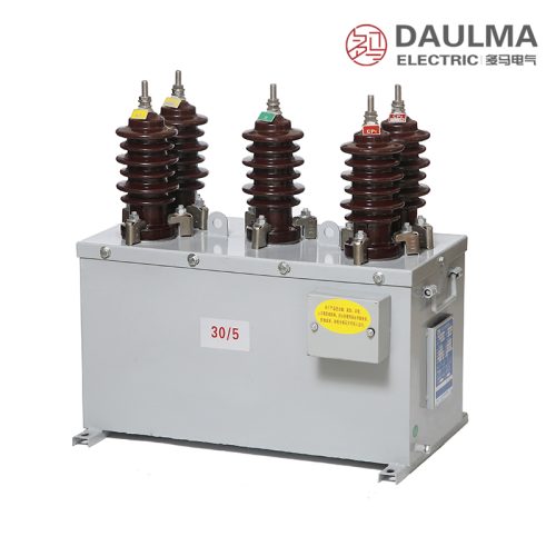
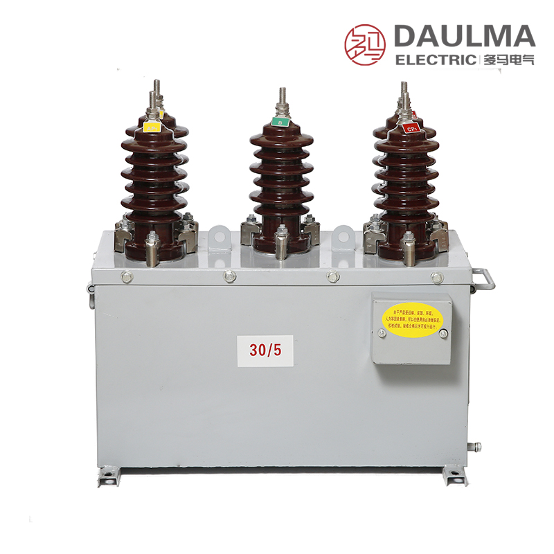
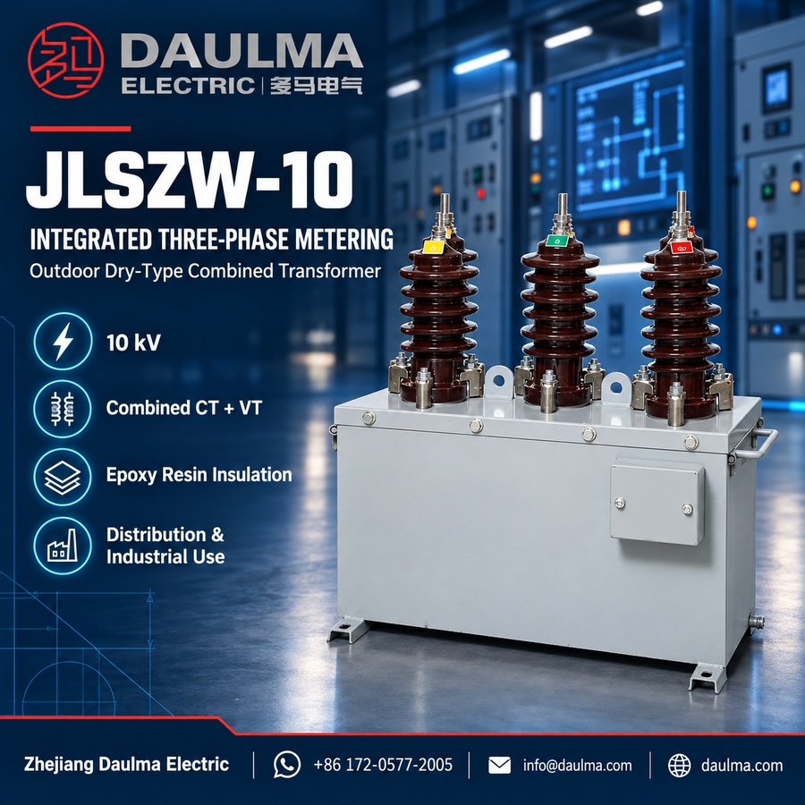
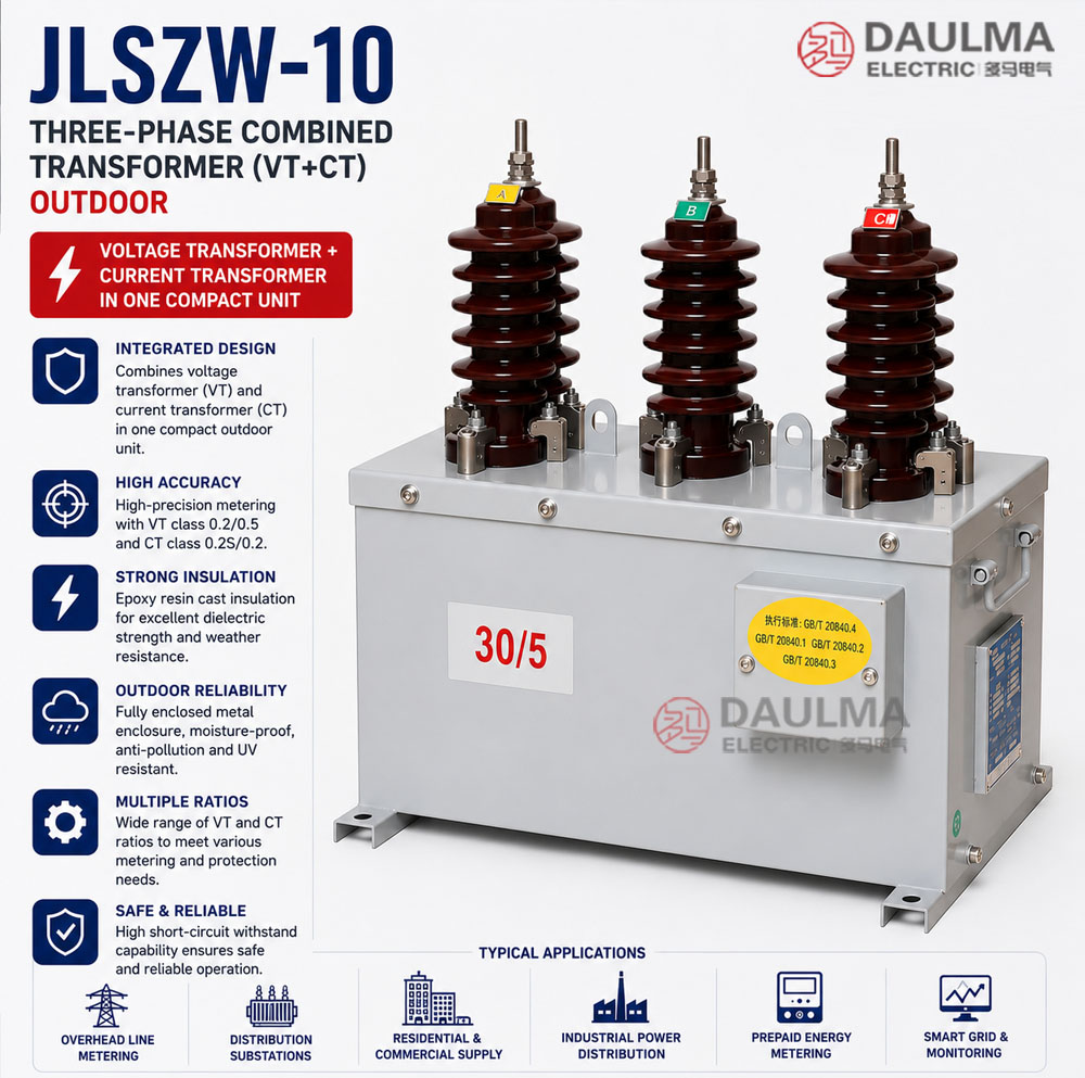
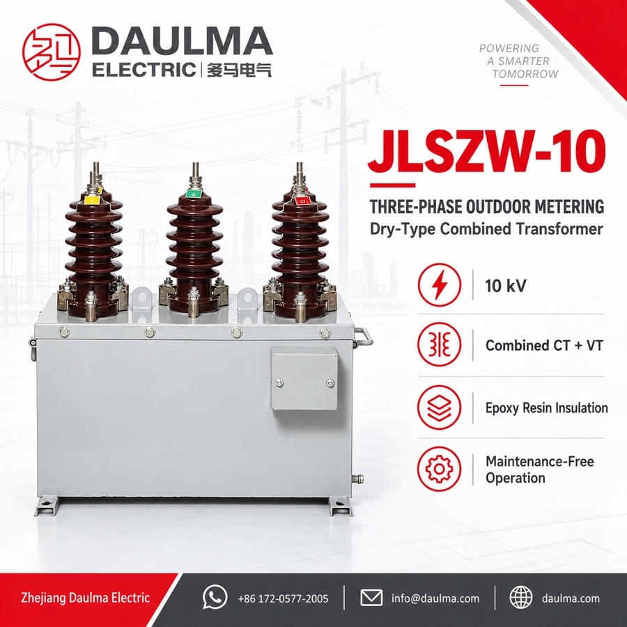
The JLSZW-10 series is a precision outdoor-rated combined instrument transformer integrating both voltage (VT) and current (CT) transformation functions in a single compact assembly. Designed for 10 kV class AC distribution systems, it delivers galvanically isolated, standardized secondary signals for accurate energy metering, relay protection, and power monitoring in three-phase three-wire networks.
Built with epoxy resin cast insulation and housed in a fully enclosed metal cabinet, the unit ensures long-term reliability under harsh outdoor conditions while maintaining high accuracy and thermal stability for revenue-grade applications.
Key Ratings Snapshot
| Parameter | Value |
|---|---|
| System Voltage Class | 10 kV |
| Rated Frequency | 50 Hz (60 Hz on request) |
| Configuration | Three-phase V/V (2 VT + 2 CT) |
| VT Ratio | 3000/100, 6000/100, or 10000/100 V |
| CT Ratio | 5-200/5 A |
| VT Accuracy | 0.2 / 0.5 class |
| CT Accuracy | 0.2S / 0.2 class |
| VT Rated Output | 15 / 30 VA per core |
| CT Rated Output | 10 VA per core |
| Insulation Level (Um/ACWV/BIL) | 12/42/75 kV (CT), up to 12/42/75 kV (VT) |
Model Designation
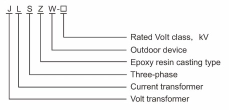
- J: Combined instrument transformer (VT + CT integrated assembly)
- L: Current transformer section designation
- S: Three-phase configuration (three-wire system)
- Z: Cast-resin (epoxy) insulated structure
- W: Outdoor service rating
- 10: Voltage class (kV)
Construction
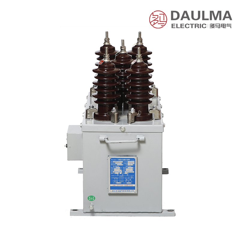
The JLSZW-10 features an integrated three-phase assembly with epoxy resin cast insulation for both VT and CT sections, ensuring superior moisture resistance, mechanical strength, and dielectric performance in outdoor environments. The VT employs an open-core design with cast windings, while the CT uses toroidal closed magnetic cores made of high-quality cold-rolled silicon steel for linear response and low phase error.
Housed in a fully sealed metal enclosure with IP-rated protection, the unit provides electromagnetic shielding, thermal dissipation, and environmental ingress resistance. The compact V/V configuration minimizes installation footprint and simplifies wiring for pole-mounted or wall-mounted metering applications in space-constrained locations.
Technical Parameters
Service Conditions
- Installation environment: Outdoor, protected from direct weather exposure
- Altitude: <= 1000 m (higher altitude requires engineering confirmation)
- Ambient temperature: -25 deg C to +40 deg C
- Relative humidity: Daily average <= 95%, monthly average <= 90%
- Pollution severity: Suitable for moderate pollution; site assessment needed for heavy industrial areas
Technical Data
| Section | Rated Voltage/Current Ratio |
Accuracy Class |
Rated Output (VA) |
Short-Circuit Withstand |
Insulation Level (kV) |
|---|---|---|---|---|---|
| VT | 3000/100, 6000/100, 10000/100 V | 0.2 / 0.5 | 15 / 30 | – | 3.6/25/40 to 12/42/75 |
| CT | 5~200/5 A | 0.2S / 0.2 | 10 | Ith: 100xI1n (1 s) Idyn: 2.5xIth (peak) |
12/42/75 |
Installation & Wiring
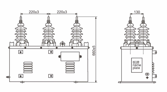
Installation Diagram
The JLSZW-10 adopts a 10 kV V/V wiring configuration suitable for three-phase three-wire two-element metering systems. Primary connections use outdoor-rated terminals with weather sealing, while secondary wiring must be routed through sealed cable glands to prevent moisture ingress. Proper grounding and phase sequence verification are essential for accurate operation.
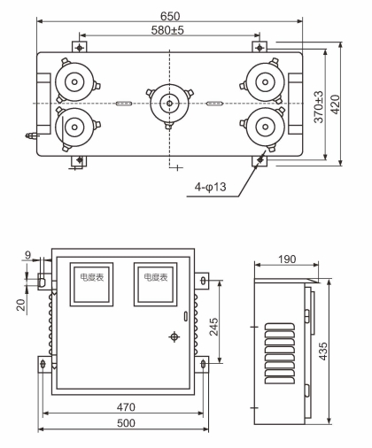
Outline Dimensions
| Dimension | Value (mm) |
|---|---|
| Height | Refer to dimensional drawing |
| Width | Refer to dimensional drawing |
| Depth | Refer to dimensional drawing |
| Mounting hole pattern | As per installation manual |
| Primary terminal spacing | Complies with 10 kV creepage requirements |
Selection & FAQs
Selection Guide
- Select VT ratio based on system line-to-line voltage (e.g., 10000/100 V for 10 kV systems)
- Choose CT ratio to match expected load current (e.g., 100/5 A for typical feeder loads)
- Specify 0.2S class CT for revenue metering with variable or low-load conditions
- Confirm insulation level (e.g., 12/42/75 kV) per local grid lightning and coordination requirements
- Verify burden compatibility between transformer output and connected metering/protection devices
- Ensure V/V connection suitability for your three-phase three-wire system without neutral
Frequently Asked Questions
Q1: Can this combined transformer handle heavy industrial pollution areas?
It is designed for moderate pollution environments. For heavy industrial areas, a detailed site assessment is required. Contact our engineering team for customized pollution level solutions.
Q2: What is the short-circuit withstand capacity of the current transformer section?
The CT section withstands a thermal short-circuit current of 100xI1n for 1 second. The dynamic peak withstand is 2.5 times the thermal current. Verify specific project requirements during ordering.
Q3: Which accuracy classes are available for the voltage transformer windings?
The VT section offers 0.2 and 0.5 accuracy classes with rated outputs of 15 VA and 30 VA respectively. Specify your exact metering requirements when requesting a quote.
Q4: How do we specify custom ratios and insulation levels for this model?
You must specify the exact VT and CT ratios, accuracy classes, burdens, and insulation levels based on local grid requirements. V/V connection is standard for three-phase metering. Confirm all details before production.
Q5: Are factory routine tests performed before shipping the JLSZW-10 transformer?
Yes, standard factory routine tests are conducted prior to shipment. Specific certification requirements or additional type tests are subject to confirmation. Please contact us for detailed test reports.
Q6: What is the primary application of this outdoor dry-type combined transformer?
This JLSZW-10 model is primarily used for outdoor three-phase power metering and relay protection in 10kV distribution networks. It integrates both voltage and current transformers in a single dry-type enclosure.
Q7: Can this unit be installed at altitudes exceeding 1000 meters?
Standard installation is rated for altitudes up to 1000 meters. For higher elevations, engineering confirmation and potential design modifications are required. Please provide your exact site altitude during the inquiry stage.