Overview
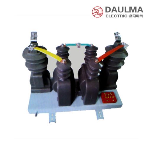
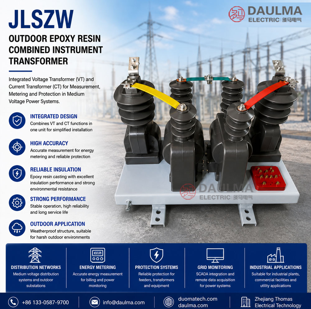
The JLSZW series outdoor epoxy resin cast combined instrument transformers integrate voltage and current measurement, energy metering, and relay protection in a single compact unit for 10kV to 35kV AC power systems. Designed for outdoor substations and industrial distribution networks, these units deliver galvanically isolated secondary signals using electromagnetic induction principles at 50 Hz frequency.
Featuring a fully sealed pillar-type structure with UV-resistant epoxy casting, the JLSZW ensures long-term reliability in harsh environments while supporting revenue-grade metering and comprehensive protection schemes through standardized VT and CT outputs.
Key Ratings Snapshot
| Parameter | Value |
|---|---|
| System Voltage Class | 10kV / 12kV / 35kV |
| Rated Frequency | 50 Hz (60 Hz on request) |
| Configuration | Combined VT + CT unit |
| VT Connection | V/V (standard); Y/Y (upgrade) |
| CT Phases | A-phase and C-phase (V/V) |
| Rated Secondary Current | 1 A or 5 A (tap-adjustable) |
| Accuracy Classes | VT: 0.2 / 0.5; CT: 0.2S / 0.5 (metering), 10P (protection) |
| Built-in Metering | Active & reactive energy meters |
| Insulation Structure | Epoxy resin cast, fully sealed |
| Lightning Protection | ZnO arrester within 1 m required |
Model Designation

- J: Combined instrument transformer (VT + CT integrated unit)
- L: Current transformer component
- S: Three-phase configuration
- Z: Outdoor support (pillar) type structure
- W: Outdoor application / weatherproof enclosure
- 6 / 10 / 35: Voltage class (kV): 6kV, 10kV, or 35kV systems
Construction
The JLSZW features an outdoor pillar-type, fully sealed epoxy resin cast enclosure that integrates both voltage and current transformers into a single robust housing. This design provides superior insulation performance, excellent resistance to UV radiation, moisture, pollution, and aging, ensuring stable operation with minimal maintenance over extended service life in demanding outdoor conditions.
Advanced epoxy casting technology prevents ingress of dust, water, and contaminants while offering high dielectric strength and anti-tracking surface properties. The unit includes ring-type CT cores, laminated VT cores, weatherproof secondary terminals, and protected compartments for integrated active and reactive energy meters.
Technical Parameters
Service Conditions
- Installation environment: Outdoor substations and distribution networks
- Altitude: <= 1000 m (higher requires derating)
- Ambient temperature: -25 deg C to +40 deg C
- Relative humidity: Daily average <= 95%, monthly average <= 90%
- Pollution severity: Up to level III per IEC 60815
- Environmental exposure: Rain, snow, ice, solar radiation, atmospheric contamination
- Seismic resistance: Intensity VII (customizable)
- Wind load: Suitable for typical regional conditions
Technical Data
| Voltage Class |
VT Primary Voltage |
VT Secondary Voltage |
Accuracy Class |
Rated Burden (VA) |
Rated Primary Current (A) |
CT Ratio | CT Accuracy (Metering / Protection) |
Ith (1s) (kA) |
|---|---|---|---|---|---|---|---|---|
| 6/10 kV | 6000/10000 V | 100 V or 100/√3 V | 0.2 / 0.5 | 50-200 | 5-600 | Tap-adjustable | 0.2S / 10P10 | 20-60 |
| 12 kV | 12000 V | 100 V or 100/√3 V | 0.2 / 0.5 | 50-200 | 10-800 | Tap-adjustable | 0.5 / 10P15 | 20-75 |
| 35 kV | 35000 V | 100 V or 100/√3 V | 0.2 / 0.5 | 50-200 | 10-800 | Tap-adjustable | 0.5 / 10P15 | 20-75 |
Installation & Wiring
Installation Diagram
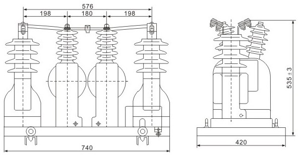
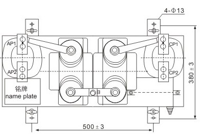
The JLSZW combined transformer is mounted on a concrete foundation or steel structure using designated anchor points. Primary connections are made via overhead line terminals or busbars, while secondary wiring is routed through weatherproof cable gland entries. Adequate clearance must be maintained for insulation, safety, and maintenance access. Zinc oxide surge arresters must be installed within 1 meter of primary terminals.
Outline Dimensions
| Model | Total Height (mm) | Base Width (mm) | Mounting Hole Spacing (mm) | Primary Terminal Height (mm) |
|---|---|---|---|---|
| JLSZW-10kV | 1250 | 320 | 280 | 1100 |
| JLSZW-35kV | 1850 | 420 | 360 | 1650 |
Selection & FAQs
Selection Guide
- Choose V/V connection for standard three-phase three-wire systems with two-element metering; select Y/Y for unbalanced loads or neutral monitoring needs.
- Specify VT accuracy class 0.2 or 0.5 and CT class 0.2S for revenue-grade metering; use 10P10/10P15 for protection cores.
- Confirm rated burden (VA) for each VT and CT core based on connected instrument loads to avoid accuracy degradation.
- Ensure ambient temperature, altitude, pollution level, and seismic zone match standard ratings or request custom engineering confirmation.
- Always include zinc oxide surge arrester within 1 m of primary terminals for effective lightning protection coordination.
- Verify secondary current preference (1 A or 5 A) and communication interface (e.g., RS485/Modbus) for integrated meters during ordering.
Frequently Asked Questions
Q1: Can this combined transformer be installed in high pollution areas?
Yes, it withstands up to level III pollution severity per IEC 60815. The epoxy resin casting provides resistance to rain, snow, and atmospheric contamination. Confirm specific site conditions with our engineering team.
Q2: What are the available current transformer ratios for the 10kV model?
Rated primary currents range from 5A to 600A with tap-adjustable CT ratios. This allows flexible selection for metering and protection circuits. Contact us with your exact primary current requirements for precise configuration.
Q3: How does this unit handle high short-circuit currents?
The 6/10 kV model supports a thermal short-circuit current (Ith) of 20 to 60 kA for 1 second. This ensures stable operation during fault conditions. Verify your system’s maximum fault level during the selection process.
Q4: Are custom deratings available for altitudes above 1000 meters?
Yes, installations above 1000m are possible but require voltage and capacity derating. Please provide your exact site altitude and ambient conditions so our factory can calculate the necessary technical adjustments.
Q5: Which routine tests are performed before factory shipment?
Standard routine tests include ratio, polarity, insulation resistance, and withstand voltage checks according to IEC standards. Specific type test certificates are subject to confirmation based on your project requirements. Request the test report template for details.
Q6: Where is this outdoor epoxy resin combined transformer typically applied?
It is designed for outdoor substations and distribution networks operating at 6kV, 10kV, or 12kV voltage classes. The combined VT and CT design saves installation space. Contact our sales team for project-specific application guidance.
Q7: When should I select the 0.2 accuracy class for metering?
Select the 0.2 class for high-precision revenue billing and the 0.5 class for standard panel indication. Rated burdens range from 50 to 200 VA to match your secondary circuit load. Specify your exact burden during ordering.