Overview
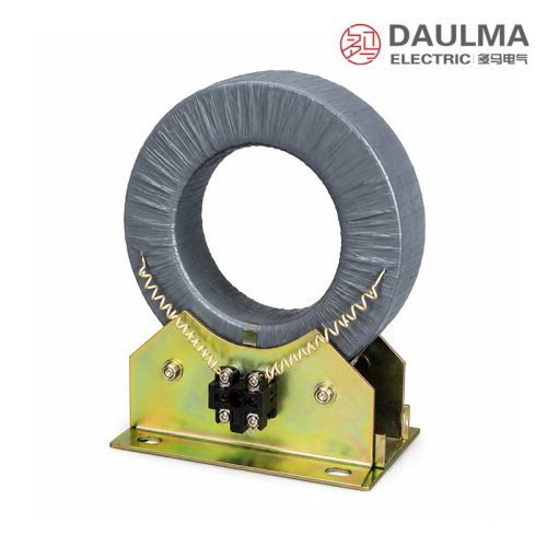
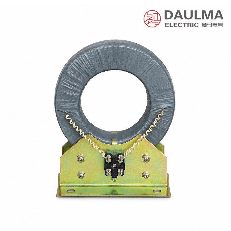
The LJ-2, LJ-4, and LJ-7 series zero-sequence current transformers are indoor-type electromagnetic devices engineered for sensitive residual (zero-sequence) current detection in low-current grounding systems. They play a critical role in ground fault protection schemes for generators, synchronous condensers, motors, and cable feeders, typically paired with DD-11/60 or equivalent residual-current relays to enable reliable fault indication or tripping.
Under normal balanced three-phase conditions, the vector sum of phase currents is near zero, resulting in negligible secondary output. During a ground fault within the protected zone, residual current generates net magnetic flux in the toroidal core, inducing a proportional secondary current that activates the connected relay for fast and accurate fault response.
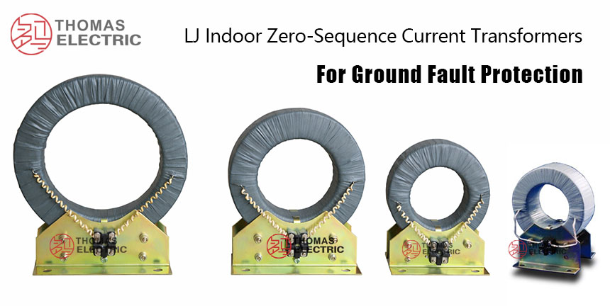
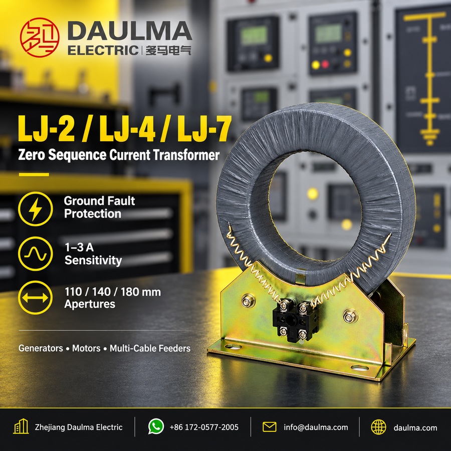
Key Ratings Snapshot
| Parameter | Value |
|---|---|
| Application | Residual current detection for ground fault protection |
| Installation Environment | Indoor only |
| System Frequency | 50/60 Hz |
| Max Cable OD | <= 50 mm |
| Secondary Insulation | 3 kV power frequency withstand (1 min) |
| Typical Relay Pairing | DD-11/60 or equivalent |
| Protected Equipment | Generators, motors, synchronous condensers, cable feeders |
| Primary Insulation | Provided by cable jacket |
| Sensitivity Range | 1â3 A |
| Adjustment Current | 0.03 A |
Model Designation
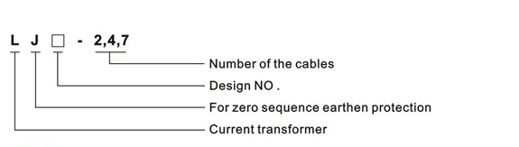
- L: Current transformer (CT)
- J: Zero-sequence / ground fault protection application
- 2 / 4 / 7: Number of cables supported (typical application reference)
Construction
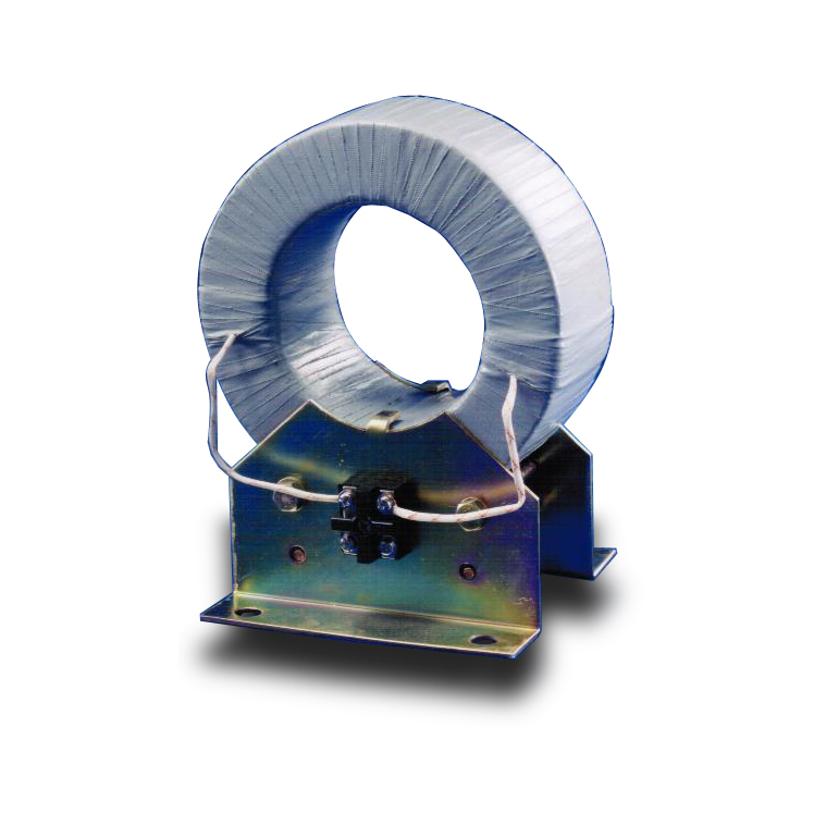
The LJ series features a ring-type toroidal core constructed from high-permeability magnetic material to ensure uniform flux distribution and high sensitivity to residual currents. The secondary winding is evenly distributed around the core to deliver stable output characteristics across operating conditions.
Mechanical installation is simplified via a robust mounting bracket with pre-positioned fixing holes, enabling secure attachment in indoor switchgear panels, control rooms, or cable trenches. Primary insulation relies on the cable jacket, while the secondary winding is rated for 3 kV power frequency withstand voltage to ground.
Technical Parameters
Service Conditions
- Installation environment: Indoor installation only
- Rated frequency: 50 Hz or 60 Hz
- Altitude: Not exceeding 1000 m above sea level
- Ambient temperature: -5 deg C to +40 deg C
- Relative humidity: Acceptable in high-humidity indoor environments if no condensation occurs
- Environmental conditions: Free from corrosive gases, explosive media, severe vibration, or mechanical shock
Technical Data
| Model | Cable Capacity |
Secondary Loop Resistance (Ω) |
Adjustment / Setting Current (A) |
Sensitivity (A) |
Typical Rated Ratio (A) |
|---|---|---|---|---|---|
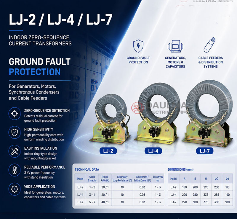
| LJ-2 | 1â2 | 10 | 0.03 | 1â3 | 20/1 |
| LJ-4 | 3â4 | 10 | 0.03 | 1â3 | 20/1 |
| LJ-7 | 5â7 | 10 | 0.03 | 1â3 | 40/1 |
Installation & Wiring
Installation Diagram
Secure the transformer using the provided mounting bracket and pre-drilled holes on a stable indoor structure. Route all phase conductors of the protected circuit through the CT windowâkeeping them compact and centeredâand ensure parallel conductors per phase pass through the same window to prevent false residual readings. Connect secondary wiring to the relay with clear identification and mechanical protection.
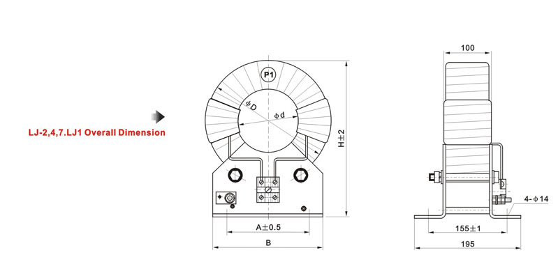
Outline Dimensions
| Model | A (mm) | B (mm) | H (mm) | phiD (mm) | phid (mm) |
|---|---|---|---|---|---|
| LJ-2 | 150 | 200 | 295 | 230 | 110 |
| LJ-4 | 220 | 280 | 335 | 285 | 140 |
| LJ-7 | 220 | 300 | 375 | 300 | 180 |
Selection & FAQs
Selection Guide
- Choose LJ-2, LJ-4 or LJ-7 from the number, outside diameter and physical arrangement of parallel cables, then verify the 110mm, 140mm or 180mm aperture.
- Confirm the expected minimum earth-fault current and that the 1–3A sensitivity range with a 0.03A setting current meets the protection study.
- Match the typical 20/1A ratio for LJ-2/LJ-4 or 40/1A for LJ-7 to the DD-11/60 or equivalent residual-current relay input.
- Check the 10Ω secondary-loop resistance requirement, wiring length and relay burden so the complete secondary circuit can operate reliably.
- Plan indoor mounting, all-phase conductor routing, one-point secondary grounding and a shorting arrangement for safe relay maintenance.
Frequently Asked Questions
Q1: What equipment can the LJ-2/4/7 protect?
The series provides residual-current signals for earth-fault protection of generators, synchronous condensers, motors and cable feeders in indoor low-current grounding systems.
Q2: What is the main difference between LJ-2, LJ-4 and LJ-7?
They are sized for different multi-cable groups: typically 1–2, 3–4 and 5–7 cables, with nominal apertures of 110mm, 140mm and 180mm respectively. Actual fit must be checked from cable dimensions.
Q3: Which relay can be connected?
The published application uses a DD-11/60 residual-current relay or an equivalent device whose input, pickup range and burden are compatible with the selected CT.
Q4: What are the typical current ratios?
LJ-2 and LJ-4 are typically 20/1A, while LJ-7 is typically 40/1A. The protection design should also confirm the 1–3A sensitivity and 0.03A setting-current data.
Q5: How should parallel cables be routed?
Every phase conductor belonging to the protected circuit, including all parallel conductors, must pass through the same aperture in the same direction and remain compactly arranged.
Q6: Does the CT provide primary system insulation?
No. The primary cable jacket provides system-voltage insulation. The CT secondary winding has a published 3kV power-frequency withstand to ground for one minute.
Q7: What is required before disconnecting the relay wiring?
Apply lockout/tagout, make the primary safe and short the CT secondary through an approved terminal before opening the circuit. Ground the secondary at one point only as required by the project standard.