Overview
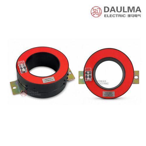
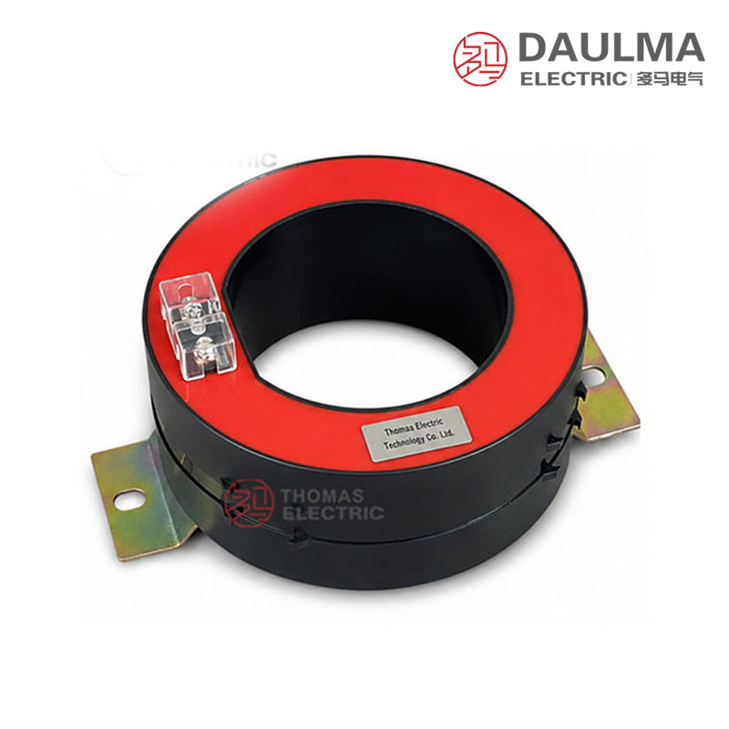
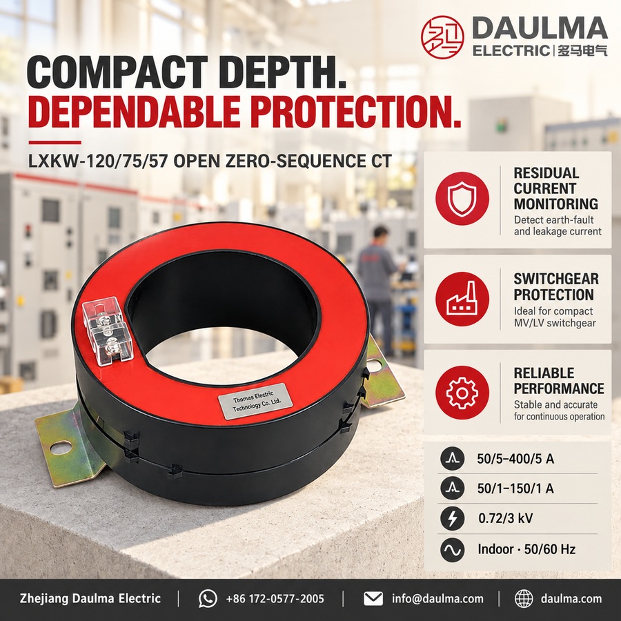
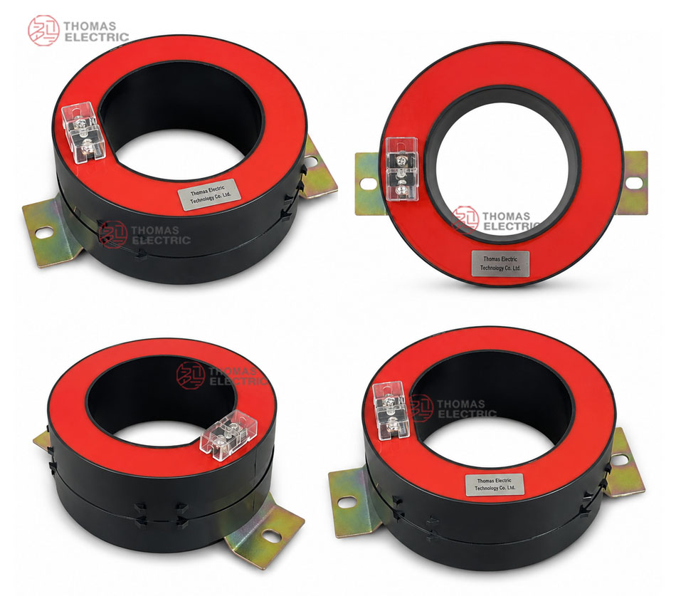
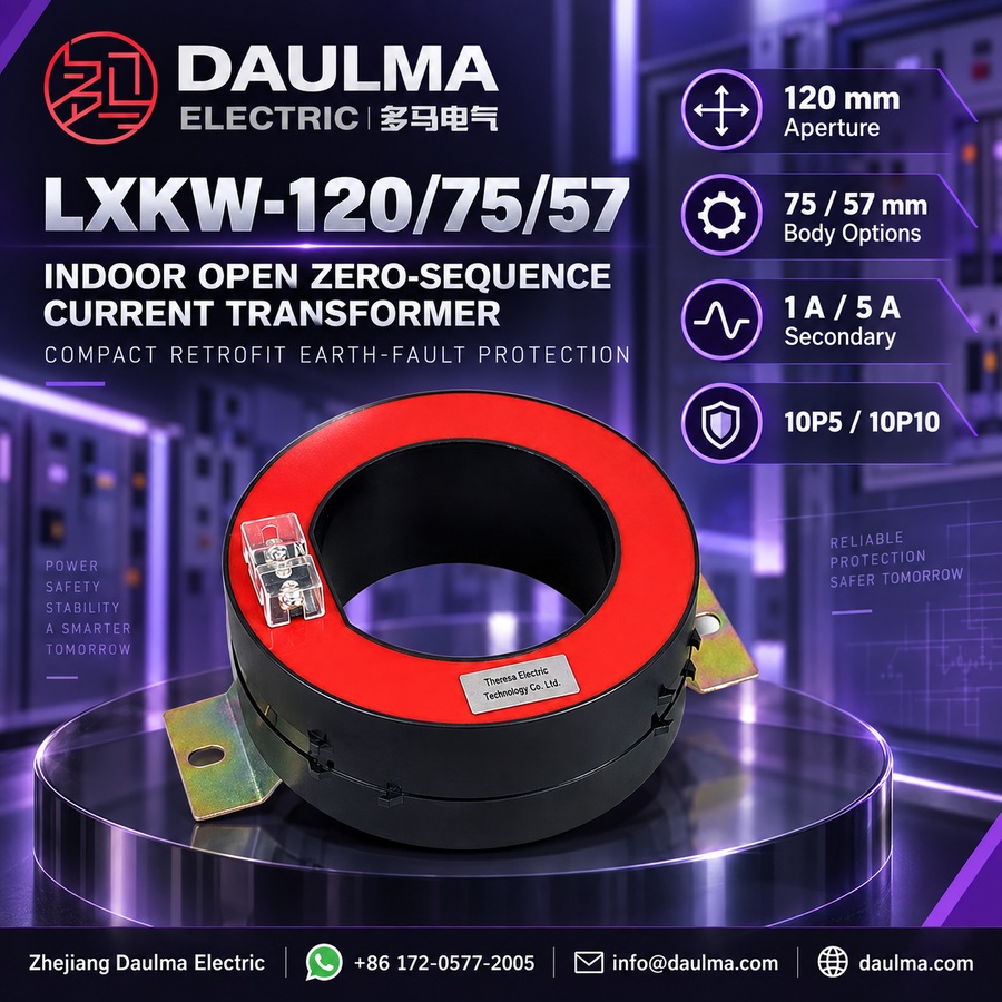
The LXKW-120/75 and LXKW-120/57 are indoor cast-resin open zero sequence current transformers rated for 0.72/3kV systems. They feature a robust cast-resin insulated body suitable for indoor environments, providing reliable electrical insulation and mechanical stability in medium-voltage applications.
These transformers offer protection accuracy classes of 10P5 or 10P10 and support secondary outputs of 5A or 1A, making them compatible with standard relay protection and monitoring equipment. They are designed for use in 50Hz or 60Hz AC power systems and comply with typical industry requirements for zero sequence current detection in switchgear, ring main units, and cable feeder protection schemes.
Key Ratings Snapshot
| Parameter | Rating |
|---|---|
| Rated voltage | 0.72/3kV |
| Rated frequency | 50Hz / 60Hz |
| Secondary current | 5A or 1A |
| Protection class | 10P5 / 10P10 |
| Insulation material | Cast-resin |
| Installation type | Indoor |
| Application | Zero sequence current detection, earth fault protection |
| Construction | Open-type |
Model Designation
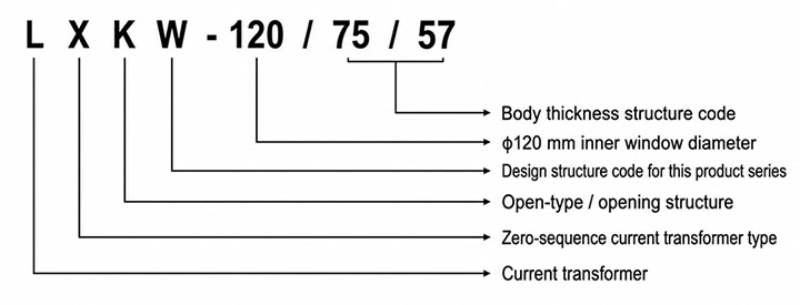
- L: Current transformer
- X: Zero sequence current transformer type
- K: Open-type / opening structure
- W: Design structure code for this product series
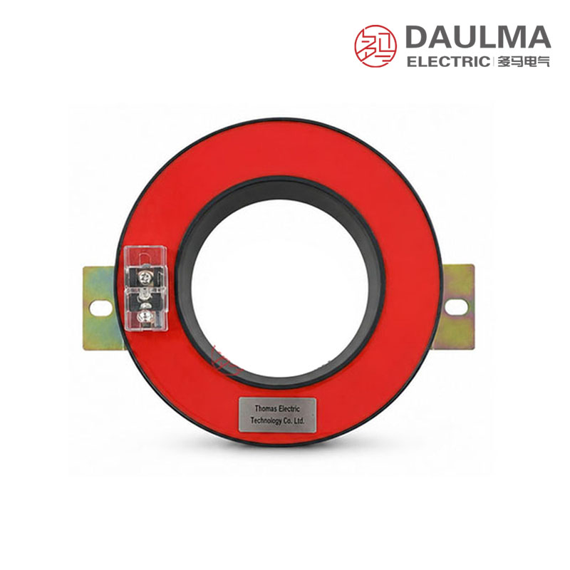
- 120: φ120 mm inner window diameter
- 75 / 57: Body thickness structure code
Construction
The LXKW-120 series features an indoor cast-resin open structure, allowing easy installation around existing cable bundles without disconnecting conductors. The core and winding assembly is fully encapsulated in high-quality cast-resin insulation, ensuring excellent dielectric strength, moisture resistance, and long-term operational reliability in enclosed switchgear environments. The open design includes precision-machined mating surfaces to maintain magnetic performance when closed around three-phase conductors. Secondary terminals are clearly marked S1 and S2 and are accessible via terminal blocks integrated into the resin housing.
Technical Parameters
Service Conditions
- Installation location: indoor
- Rated insulation level: 0.72/3kV
- Rated frequency: 50Hz / 60Hz
- Ambient temperature: -25°C to +40°C
- Installation environment: Free from severe vibration, corrosive gas, conductive dust, explosive medium, heavy moisture and serious pollution.
- Conductor routing: All phase conductors of the protected circuit should pass through the same transformer window in the same direction.
- Mechanical stress: The cable or conductor group should pass through the window without mechanical stress on the transformer body.
- Special requirements: For special cable diameter, relay model, wiring distance, burden or protection setting requirements, technical confirmation is recommended before ordering.
Technical Parameters
The LXKW-120/75/57 is an indoor cast-resin open zero sequence current transformer rated for a 0.72/3kV insulation level, designed for operation at 50Hz or 60Hz within an ambient temperature range of -25°C to +40°C. It complies with GB 20840.1-2010 and GB 20840.2-2014 standards and supports secondary currents of 1A or 5A across multiple primary current ratios.
| Type | Rated Current Ratio (A) | Rated Output 10P5 (VA) | Rated Output 10P10 (VA) |
|---|---|---|---|
| LXKW-120/75 | 50/5 | 1.5 | – |
| LXKW-120/75 | 75/5 | 2.5 | 0.5 |
| LXKW-120/75 | 100/5 | 3.75 | 1 |
| LXKW-120/75 | 150/5 | 5 | 2.5 |
| LXKW-120/75 | 200/5 | 7.5 | 3.75 |
| LXKW-120/75 | 300-400/5 | 10 | 5 |
| LXKW-120/75 | 50/1 | 1.5 | – |
| LXKW-120/75 | 75/1 | 2.5 | 0.5 |
| LXKW-120/75 | 100/1 | 3.75 | 1 |
| LXKW-120/75 | 150/1 | 5 | 2.5 |
Note: If user’s data go beyond the above-mentioned scopes, they may be subject to an agreement between manufacturer and purchaser.
Installation & Wiring
Installation Diagram
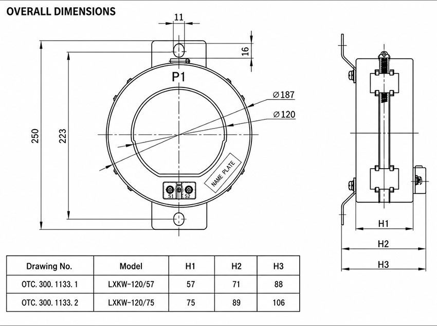
The LXKW-120/75 and LXKW-120/57 models are installed around the three-phase conductor group, which passes through the φ120 mm inner window. The transformer is secured to the cabinet base or a mounting bracket using appropriate hardware to prevent movement or vibration during operation. Ensure the conductor group is centered within the window for optimal zero sequence current detection.
Wiring Diagram
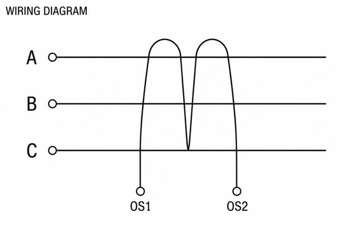
Wiring connections are made at the secondary terminals as follows:
- S1: Secondary output terminal – connect to the relay or monitoring input according to polarity requirements.
- S2: Secondary output terminal – connect to the relay or monitoring return terminal.
- Ground / shield terminal (where provided): Connect in accordance with the project grounding and protection scheme.
All phase conductors of the protected circuit must pass through the same window in the same direction. Never pass only one phase conductor when used for zero sequence protection. Verify secondary wiring continuity, terminal tightness, and relay settings before energizing.
Selection & FAQs
Selection Guide
- Verify that the complete three-phase cable group fits the 120mm aperture with adequate insulation clearance and no mechanical load on the CT body.
- Choose LXKW-120/75 when higher VA output is required or LXKW-120/57 where installation depth is limited, subject to the dimensional drawing.
- Select a 1A or 5A secondary and a catalogue ratio suited to the relay input and expected residual-fault current.
- Confirm whether 10P5 or 10P10 is required and calculate relay plus lead burden; low ratios and the thinner 57mm model have lower available output.
- Review indoor conditions, mounting access, S1/S2 polarity and the routing of all phase, screen, armour and grounding conductors before ordering.
Frequently Asked Questions
Q1: What is the LXKW-120/75/57 used for?
It senses zero-sequence current for earth-fault protection or residual-current monitoring in indoor switchgear, ring-main units and cable feeders.
Q2: What do 120, 75 and 57 mean in the model?
The 120 identifies the 120mm circular aperture. The 75 and 57 identify different body-thickness structures, which affect installation dimensions and obtainable rated output.
Q3: Can it be added to an existing cable circuit?
Yes. The core opens so it can be installed around an existing three-phase cable group without disconnecting the primary conductors, provided the split faces can be fully aligned and secured.
Q4: Which current ratios are available?
Catalogue options cover 50/5A–400/5A and 50/1A–150/1A. Available VA and 10P class vary with ratio and body thickness, so the complete configuration must be checked.
Q5: When should the 75mm version be preferred?
Choose the 75mm structure when the protection circuit needs more VA output. The 57mm version is more compact but generally supplies a lower burden at the same ratio and class.
Q6: How should cables and screens pass through the CT?
All phase conductors must pass through the aperture together in the same direction. Cable screens, armour and grounding conductors must follow the project scheme so they do not bypass or falsely create residual current.
Q7: What must be checked before energizing?
Confirm the split core is clean and fully closed, mounting is secure, conductors are centered, S1/S2 polarity is correct, terminals are tight, the relay setting is verified and the secondary circuit is never left open.