Overview
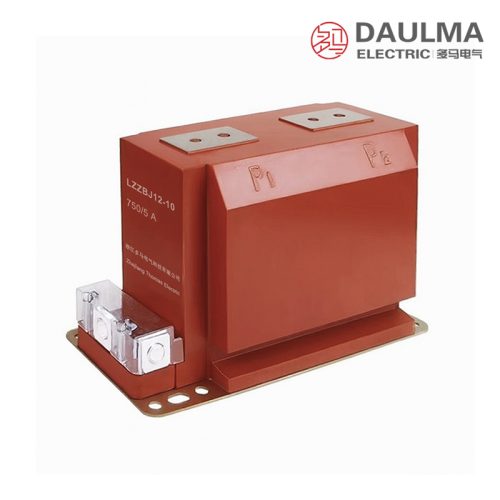
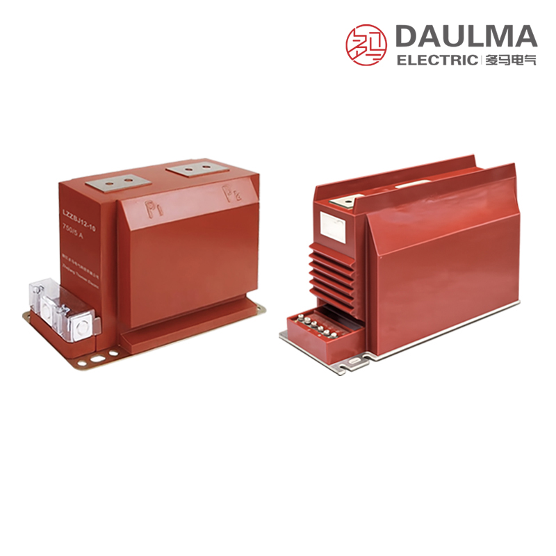
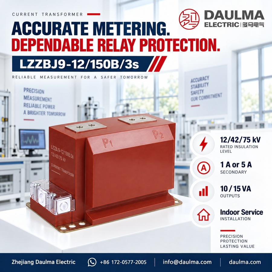
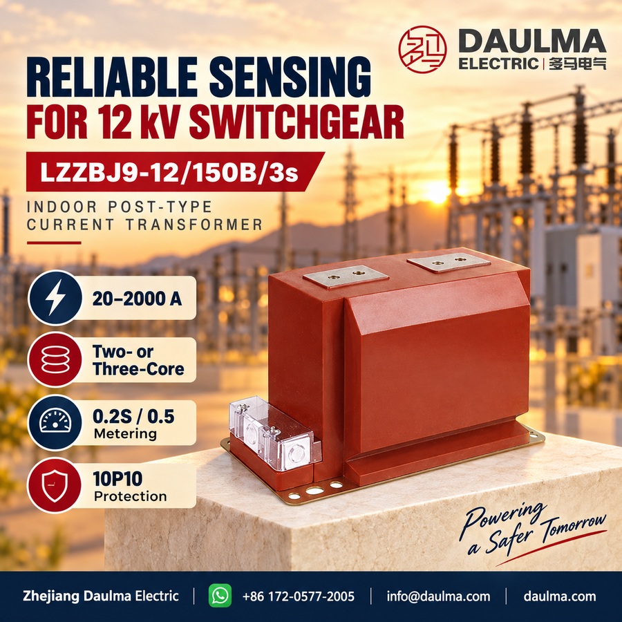
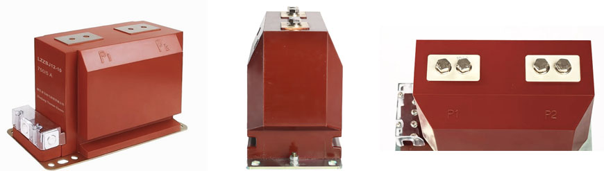
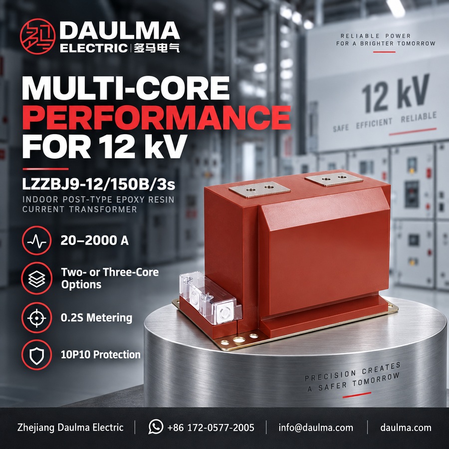
The LZZBJ9-12/150B/3s is a fully-enclosed, post-type current transformer designed for 12 kV class indoor medium-voltage systems. It features cast-resin (epoxy) insulation, providing high dielectric strength, moisture resistance, and long-term reliability in compact switchgear and ring main unit installations.
Engineered for both metering and protection applications, it supports accuracy classes such as 0.2S, 0.5, and 10P10, with primary currents from 20 A to 3000 A and secondary outputs of 1 A or 5 A. The transformer complies with GB 1208-1997, IEC 61869-1/-2, and GB/T 20840.1/20840.2 standards, ensuring performance in 50 Hz (or 60 Hz) AC networks under pollution degree II conditions.
Key Ratings Snapshot
| Parameter | Rating |
|---|---|
| System voltage class | 12 kV |
| Rated frequency | 50 Hz (60 Hz optional) |
| Primary current range | 20 A – 3000 A |
| Rated secondary current | 1 A or 5 A |
| Accuracy classes | 0.2S / 0.5 (metering), 10P10 (protection) |
| Insulation level | 12 / 42 / 75 kV |
| Burden power factor | cosφ = 0.8 (lagging) |
| Short-circuit withstand | Ith (1 s) and Idyn (peak) per specification |
| Applicable standards | GB 1208-1997; IEC 61869-1 / -2; GB/T 20840.1 / 20840.2 |
Model Designation
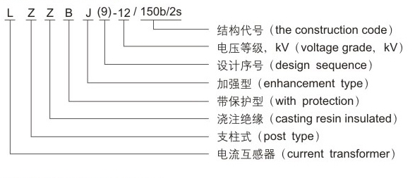
- L: Current transformer (CT)
- Z: Indoor support (pillar) type
- Z: Cast-resin (epoxy) insulated, fully enclosed structure
- B: Protection configuration available (metering/protection application)
- J: Reinforced design
- 9: Design code (platform/iteration)
- 12: Voltage class (kV)
- 150B/3s: Mechanical variant code for installation and structural compatibility
Construction
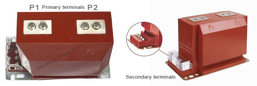
The LZZBJ9-12/150B/3s employs a fully-enclosed epoxy resin cast construction, delivering excellent insulation integrity, mechanical robustness, and resistance to humidity and contamination. Its post-type form factor enables space-efficient mounting in indoor switchgear while maintaining required electrical clearances and creepage distances. The core utilizes a high-permeability toroidal ring design that ensures measurement accuracy, low losses, and thermal stability across the operating range. Primary and secondary windings are fully integrated within the cast body, forming a unified insulation system rated for long-term service in demanding indoor environments up to pollution degree II.
Technical Parameters
Service Conditions
- Installation environment: Indoor installation only
- Altitude: Not exceeding 1000 m above sea level (higher altitude shall be specified for engineering confirmation)
- Ambient temperature: −5 °C to +40 °C
- Relative humidity: Daily average ≤ 95%, monthly average ≤ 90% (at +20 °C reference)
- Environmental conditions: Free from corrosive gases or vapors; free from explosive or flammable media; no severe vibration, mechanical shock, or impact
- Pollution class: Class II per IEC 60815
Technical Parameters
The LZZBJ9-12/150B/3s is a fully-enclosed cast-resin current transformer designed for indoor use in 12 kV class AC systems (50 Hz). It operates within an ambient temperature range of −5 °C to +40 °C and at altitudes up to 1000 m, complying with IEC standards. The device supports primary current ratings from 20 A to 2000 A with multiple accuracy class combinations for metering and protection applications.
Current Transformer Data
| Rated Primary Current (A) |
Accuracy Class (Protection/ Measurement) |
Rated Output (VA) |
Short-Time Thermal Current |
Dynamic Current |
|---|---|---|---|---|
| 20~100 | 0.2S/10P10 | 10/15 | 150I1n | 375I1n |
| 150~200 | 0.2S/0.5/10P10 | 10/15/15 | 21.5 kA | 55.4 kA |
| 300~400 | 0.5/10P10 | 10/15 | 31.5 kA | 80 kA |
| 500~600 | 0.2/10P10 | 10/15 | 45 kA | 112.5 kA |
| 800 | 0.2S/10P10 | 10/15 | 63 kA | 130 kA |
| 800 | 0.2S/0.5/10P10 | 10/15/15 | 63 kA | 130 kA |
| 800 | 0.5/10P10 | 10/10 | 63 kA | 130 kA |
| 800 | 0.2/10P10 | 10/15 | 63 kA | 130 kA |
| 1000 | 0.2S/10P10 | 10/15 | 80 kA | 160 kA |
| 1000 | 0.2S/0.5/10P10 | 10/15/15 | 80 kA | 160 kA |
| 1000 | 0.5/10P10 | 10/10 | 80 kA | 160 kA |
| 1000 | 0.2/10P10 | 10/15 | 80 kA | 160 kA |
| 1500 | 0.2/10P10 | 10/15 | 100 kA | 160 kA |
| 2000 | 0.2/10P10 | 10/15 | 100 kA | 160 kA |
Installation & Wiring
Installation
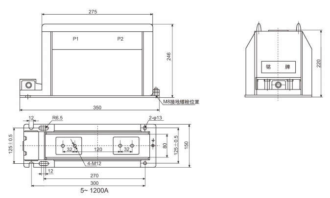
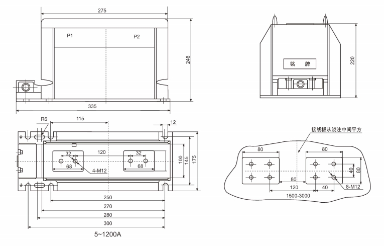
- Outline dimensions and mounting details are provided in the dimensional drawings.
- The transformer shall be securely mounted using the designated fixing holes with appropriate torque specifications.
- Primary conductor connection may be made via busbar or bolted terminals.
- Adequate clearance shall be maintained for insulation, heat dissipation, and maintenance access.
- Secondary wiring shall use appropriate cable size to minimize burden contribution.
Selection & FAQs
Selection Guide
- Select from the detailed 20A–2000A ratio schedule. The overview mentions up to 3000A, but no 3000A technical row is supplied; require a separate data sheet and drawing for any ratio above 2000A.
- Choose the number of cores by application. Two-core options pair measurement with 10P10 protection, while selected ratios list a three-core 0.2S/0.5/10P10 arrangement with 10/15/15VA outputs.
- Match 1A or 5A secondary to the entire burden circuit. Calculate meter or relay input, cable resistance, test block and terminals, then confirm the listed output for each core and ratio.
- Do not infer a 3-second fault rating from the suffix. The source treats “150B/3s” as a mechanical variant but describes the table as 1-second Ith; obtain certified short-time current and duration for the exact product.
- Approve the complete 12kV interface. Confirm 12/42/75kV insulation, pollution and altitude requirements, primary connection, mounting-hole pattern, torque, terminal allocation, grounding and maintenance clearances.
Frequently Asked Questions
Q1: Can this post-type current transformer be installed in outdoor environments?
No, it is strictly designed for indoor installation only. The operating environment must be free from corrosive gases, explosive media, and severe vibration. Contact us for outdoor-rated alternatives.
Q2: What is the short-time thermal current rating for 100A primary?
For primary currents between 20 A and 100 A, the short-time thermal current is 150 times the rated primary current. The dynamic current rating is 37 times the peak value. Specify your exact primary current for precise calculation.
Q3: Which accuracy class combination is provided for metering and protection?
The standard configuration offers a 0.2S accuracy class for measurement and 10P10 for protection. This ensures high precision for revenue metering alongside reliable fault detection. Confirm specific VA burden requirements with our engineering team.
Q4: How does high altitude affect the installation of this 12kV CT?
Standard installation is limited to altitudes not exceeding 1000 m above sea level. For deployments at higher elevations, dielectric strength and thermal dissipation require engineering confirmation. Please provide your exact site altitude during the inquiry.
Q5: Are custom primary current ratings available beyond the 2000A maximum?
The standard range covers primary currents from 20 A to 2000 A. Ratings outside this scope are subject to technical confirmation and custom manufacturing. Submit your single-line diagram for feasibility assessment.
Q6: Do specific factory tests apply before shipping this epoxy CT?
Routine and type testing details are subject to confirmation based on your specific project requirements. We comply with IEC standards for 12 kV class equipment. Contact our sales team for the detailed test certificate scope.
Q7: Where is this 12kV indoor current transformer typically applied?
It is designed for 12 kV class AC systems operating at 50 Hz. Typical applications include indoor switchgear, power distribution panels, and relay protection circuits. Verify pollution class II compatibility for your specific facility.
Q8: Is this post-type current transformer compliant with IEC standards?
Yes, the device is manufactured in compliance with IEC standards for instrument transformers. Pollution severity is rated Class II per IEC 60815. Request the full compliance declaration from your regional distributor.