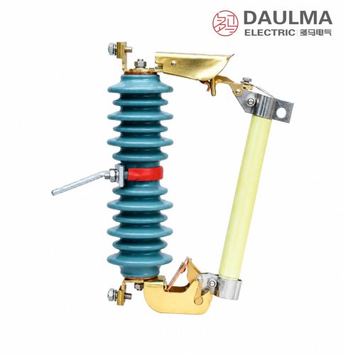
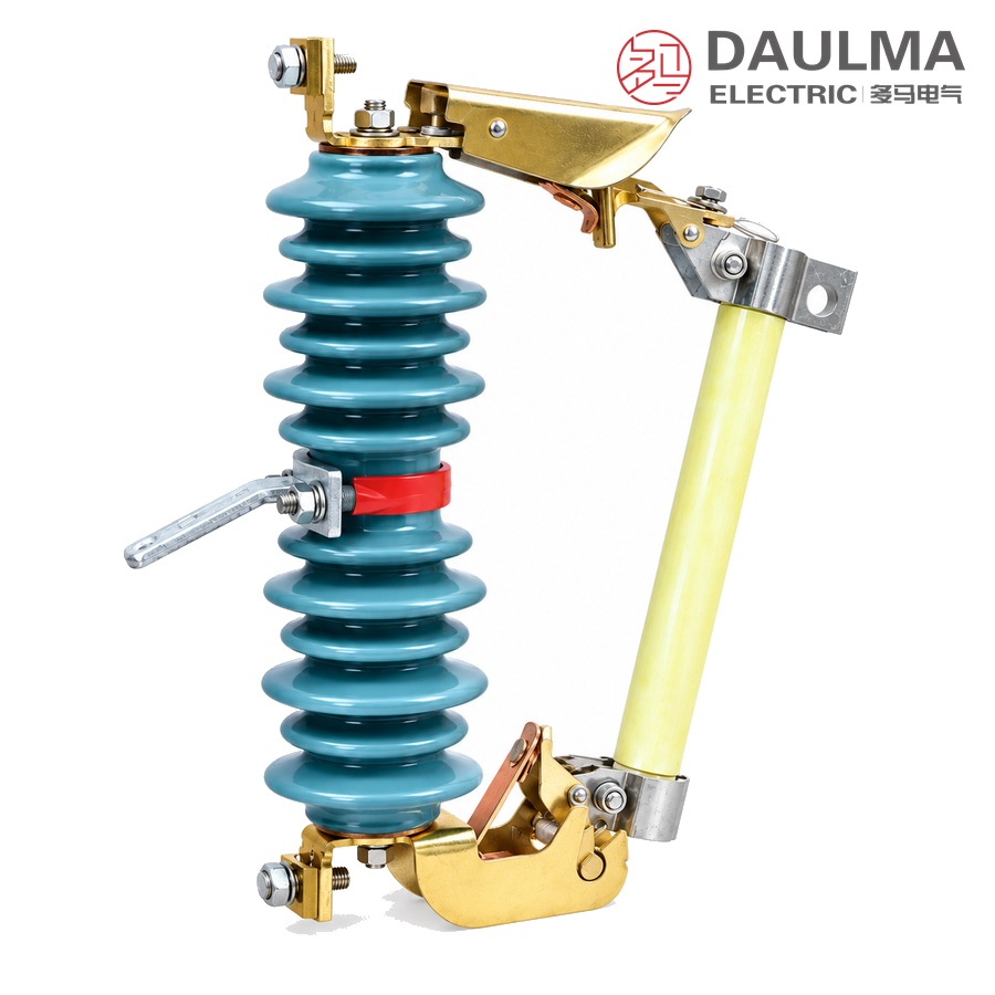
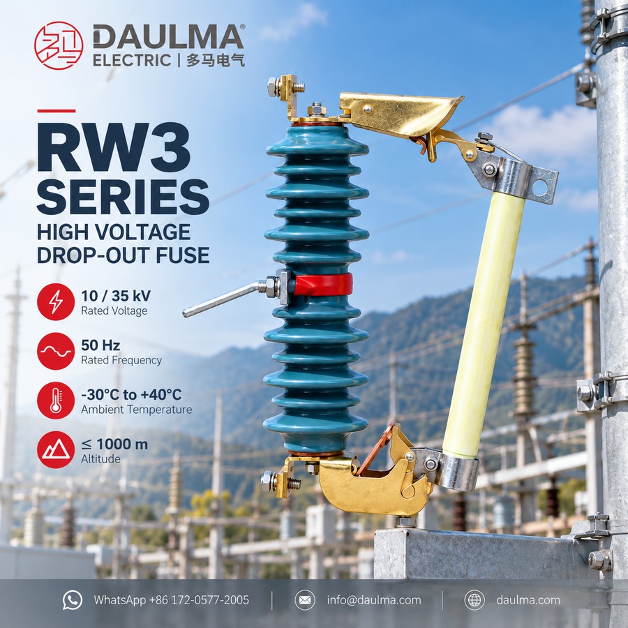
The RW3-10KV high-voltage dropout fuse cutout is an outdoor protective device installed on the high-voltage side of a distribution transformer or on a branch line of an overhead distribution network, where it gives short-circuit and overload protection for the transformer and the line. The series is applied in power systems of 35 kV and below at 50 Hz, and within it a model carries a rated voltage of 10 kV, 12 kV or 35 kV as tabulated.
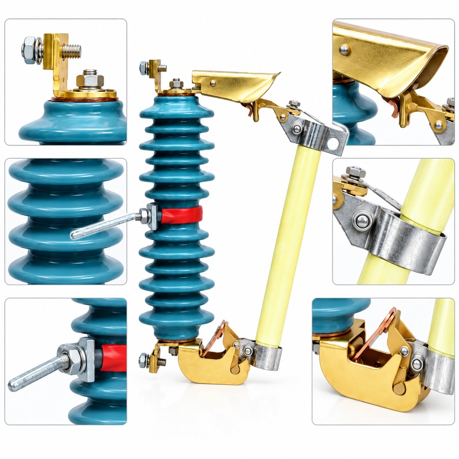
A cutout has two parts, an insulating mounting frame and a fuse tube, and the tube hangs from the frame between a pair of contacts so that the circuit passes through it. When the fuse link melts, the tube is released, drops away and leaves the clearly visible open position that shows which line or transformer has been cut off.
Model Designation
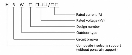
The designation is read from left to right: the letters give the insulating support, the device and its use, and the figures after them give the design number, the rated voltage and the rated current.
- H: composite insulating support, that is, without porcelain support
- R: fuse
- W: outdoor type
- Box after W: design number
- Box after the design number: rated voltage, kV
- Box after the slash: rated current, A
So RW3-10/100(200) is the outdoor fuse cutout of design 3 with a porcelain insulating support, a rated voltage of 10 kV and the tabulated rated current of 100 (200) A, and HRW3-10/100(200) is the same cutout with a composite insulating support in place of the porcelain one. A model that carries no H has no composite support, and the porcelain-insulator and composite-insulator models of the series are tabulated with the same electrical ratings.
Construction
The static contacts are fixed to the two ends of the insulating mounting frame and the moving contacts to the two ends of the fuse tube. The tube itself is built in two layers, an inner arc-quenching tube inside an outer tube of phenolic paper or of epoxy glass cloth.
The load-break cutouts of the series are additionally fitted with elastic auxiliary contacts and an arc-extinguishing hood, which is what allows them to make and break load current rather than only to protect the circuit against fault current.
Operation on a Fault
In normal service the fuse tube is held in its closed position by the tension of the fuse link. When a fault occurs the fuse link melts rapidly and an arc forms; the arc heats the inner arc-quenching tube, which decomposes into a large volume of gas and raises the pressure inside the tube, and that gas blows longitudinally along the bore so the arc is stretched out and extinguished.
With the fuse link melted, the lower moving contact loses its tension and turns downward, the locking mechanism releases the fuse tube, and the tube drops to leave a clearly visible open position.
Making and Breaking Load Current
Where load current has to be interrupted, an insulating rod is used to pull the moving contact open while the main and static contacts remain in touch, and as the rod continues to draw the moving contact the auxiliary contacts separate as well. The arc is then struck between the auxiliary contacts, is lengthened in the slits of the arc-extinguishing hood, and the gas the hood generates extinguishes it at the current zero.
Technical Parameters
Service Conditions
- Ambient temperature: +40℃ upper, -30℃ lower
- Altitude: Not more than 1000 m
- Wind speed: Not more than 35 m/s
- Not installed in: Places with combustible material or explosion hazard
- Not installed in: Places with violent vibration or impact
- Not installed in: Places with abnormal electrochemical action, severe air pollution or smoke
Technical Data
| Model | Rated voltage, kV | Rated current, A | Breaking current, kA | Lightning impulse withstand voltage, kVp | Power-frequency withstand voltage, kV r.m.s | Creepage distance, mm | Weight, kg |
|---|---|---|---|---|---|---|---|
| RW3-10/100(200) | 10 | 100 (200) | 6.3(8.0) | 110 | 42 | 320 | 6.3 |
| HRW3-10/100(200) | 10 | 100 (200) | 6.3(8.0) | 110 | 42 | 350 | 2.5 |
| RW4-10/100(200) | 10 | 100 (200) | 6.3(8.0) | 110 | 42 | 320 | 6.4 |
| RW7-10/100(200) | 10 | 100 (200) | 6.3(8.0) | 110 | 42 | 320 | 6.4 |
| RW10-10F/100(200) | 10 | 100 (200) | 6.3(8.0) | 110 | 42 | 320 | 7.0 |
| HRW10-10F/100(200) | 10 | 100 (200) | 6.3(8.0) | 110 | 42 | 350 | 3.8 |
| RW11-10/100(200) | 10 | 100 (200) | 6.3(8.0) | 110 | 42 | 320 | 7.8 |
| HRW11-10(200) | 10 | 100 (200) | 6.3(8.0) | 110 | 42 | 350 | 3.5 |
| PRWG1-12/100(200) | 12 | 100 (200) | 6.3(8.0) | 110 | 42 | 320 | 8.8 |
| RW5-35/100(200) | 35 | 100 (200) | 6.3(8.0) | 170 | 70 | 870 | 30 |
| HRW5-35/100(200) | 35 | 100 (200) | 6.3(8.0) | 170 | 70 | 870 | 15 |
Installation & Wiring
Installation and Commissioning
The cutout is fixed on the high-voltage side of the distribution transformer or on the branch line of the overhead network, the fuse tube is seated between the frame contacts with the fuse link tensioned so that the contacts close, and operation is carried out with an insulating rod.
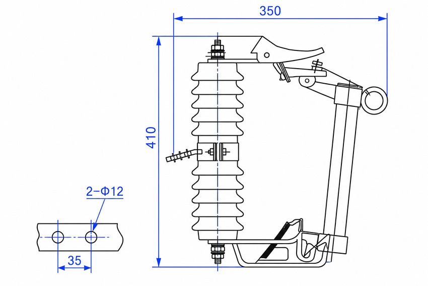
Outline and Installation Dimensions
- Overall: the outline drawing dimensions the assembled cutout at 410 mm vertically and 350 mm horizontally.
- Mounting: the drawing details a strip drilled for two holes of 12 mm diameter at 35 mm pitch.
- Creepage distance: 320 mm on the porcelain-insulator models, 350 mm on the polymer-insulator models of the 10 kV and 12 kV class, and 870 mm on the 35 kV models.
- Weight: from 2.5 kg on the polymer-insulator load-break type to 30 kg on the 35 kV model, as tabulated.
Component Reference
- Insulating mounting frame: carries the static contacts at its two ends.
- Static contacts: fixed to the two ends of the insulating mounting frame.
- Fuse tube: carries the moving contacts at its two ends and hangs between the frame contacts.
- Moving contacts: fitted to the two ends of the fuse tube.
- Inner arc-quenching tube: the inner layer of the fuse tube, which decomposes into gas under the heat of the arc.
- Outer tube: the outer layer of the fuse tube, of phenolic paper or of epoxy glass cloth.
- Auxiliary contacts: elastic contacts fitted to the load-break type.
- Arc-extinguishing hood: fitted to the load-break type; its slits lengthen the arc and the gas it generates extinguishes the arc at the current zero.
- Locking mechanism: releases the fuse tube once the lower moving contact has turned downward after the fuse link melts.
Applications
- High-voltage side of distribution transformers
- Branch lines of overhead distribution networks
- Overload and short-circuit protection of transmission lines and power transformers
- Making and breaking of rated load current on the load-break type
Selection & FAQs
Selection Guide
- Take the rated voltage of the model. The series is applied in systems of 35 kV and below, and within it the tabulated models are built for 10 kV, 12 kV or 35 kV; the insulation of a 10 kV cutout, at 110 kVp lightning impulse and 42 kV r.m.s power-frequency withstand, cannot be used on a 35 kV line, where the tabulated models carry 170 kVp and 70 kV r.m.s.
- Choose the insulator. The porcelain-insulator models of the 10 kV and 12 kV class are tabulated at 320 mm creepage distance; the polymer-insulator models of the same voltage, which carry the H prefix, are tabulated at 350 mm and are markedly lighter, 2.5 kg against 6.3 kg on the RW3 size.
- Decide whether load switching is required. A cutout used only as the protection of a transformer or a branch line needs no more than the fuse tube and the frame contacts; where the line must also be opened and closed in service, take the load-break type with elastic auxiliary contacts and an arc-extinguishing hood, which is the only version of the series that makes and breaks load current.
- Check the current against the protected circuit. The tabulated rated current of every model is 100 (200) A with a breaking current of 6.3(8.0) kA, so confirm the full-load current of the transformer or the fault level of the line against those figures before ordering.
- Match the site to the service conditions. The cutout is an outdoor device for altitudes not more than 1000 m, wind speeds not more than 35 m/s and ambient temperatures between -30 and +40 degrees, and it is not installed where there is combustible material or explosion hazard, violent vibration or impact, or abnormal electrochemical action, severe air pollution and smoke.
FAQs
Q1: What is the RW3-10KV used for?
It is an outdoor high-voltage dropout fuse cutout installed on the high-voltage side of a distribution transformer or on a branch line of an overhead distribution network, where it protects the transformer and the line against short circuit and overload. The series is applied in power systems of 35 kV and below at 50 Hz, and the RW3-10KV itself is a 10 kV model. The load-break versions of the series also make and break load current.
Q2: How does a dropout fuse cutout clear a fault?
The fuse tube is held in its closed position by the tensioned fuse link. On a fault the fuse link melts rapidly and an arc forms; the arc heats the inner arc-quenching tube, which decomposes into a large volume of gas, the pressure inside the tube rises, and the gas blows longitudinally along the bore so the arc is stretched and extinguished. The melted fuse link releases the lower moving contact, which turns downward, the locking mechanism lets go of the tube, and the tube drops to give a clearly visible open position.
Q3: What is the difference between the porcelain and the polymer insulator models?
Both carry the same contacts and the same fuse tube, and the electrical ratings tabulated for them are the same. The difference is the insulating mounting frame: the porcelain models of the 10 kV and 12 kV class are tabulated at 320 mm creepage distance and the polymer-insulator models, which carry the H prefix, at 350 mm, and the polymer frame is much lighter, 2.5 kg against 6.3 kg on the RW3 size. On a 35 kV line the two versions are tabulated at the same 870 mm creepage distance and differ only in weight.
Q4: Can the cutout be opened with load current flowing?
Only on the load-break type. Those cutouts are fitted with elastic auxiliary contacts and an arc-extinguishing hood in addition to the main contacts, so an insulating rod first opens the moving contact while the main and static contacts are still in touch, then separates the auxiliary contacts, and the arc drawn between them is lengthened in the slits of the hood and extinguished by the gas the hood generates at the current zero. A protection-only cutout has no auxiliary contacts and no hood, so it is not used to interrupt load current.
Q5: How does it compare with a load break switch on the same feeder?
They do different jobs. The dropout fuse cutout is a protective device: it carries load current, and it interrupts fault current by melting a fuse link and dropping the tube, which is also what gives the visible open position a line patrol can read. A switch such as the FZW32-12 outdoor vacuum load break switch is an operating device, switched on and off deliberately and repeatedly, and where a short circuit has to be cleared from an indoor feeder the FZN21A-12D or the FZN25-12D does it with a switch-fuse combination unit on the same frame. On overhead lines the cutout is the usual protection of a transformer, and the two are often used together, with the switch as the operating device and the cutout as the protection and the visible break.
Q6: What has to be checked before a cutout is put on a line?
Three things. The rated voltage of the model has to match the class of the line, since the tabulated 10 kV, 12 kV and 35 kV models carry different insulation levels and creepage distances. The rated current and the breaking current have to cover the full-load current of the transformer or the line and the fault level at the point of installation. And the site itself has to be within the service conditions, an outdoor location at not more than 1000 m altitude and wind speeds not more than 35 m/s, between -30 and +40 degrees, and free from combustible material and explosion hazard, from violent vibration or impact, and from abnormal electrochemical action, severe air pollution and smoke.