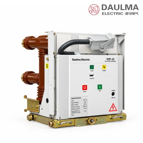
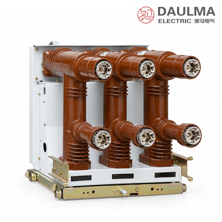
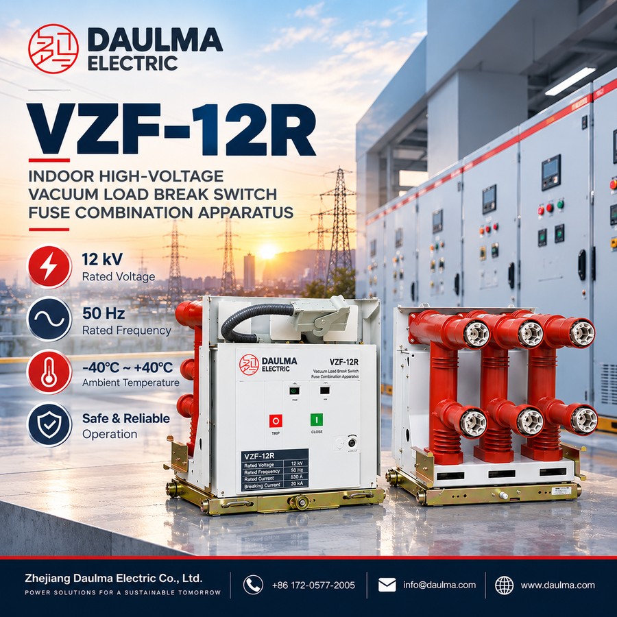
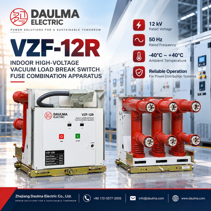
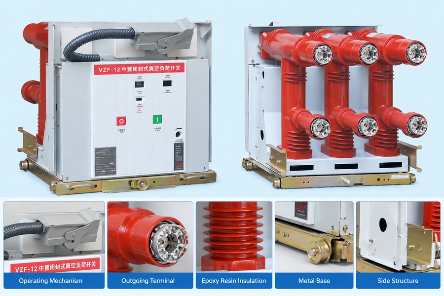
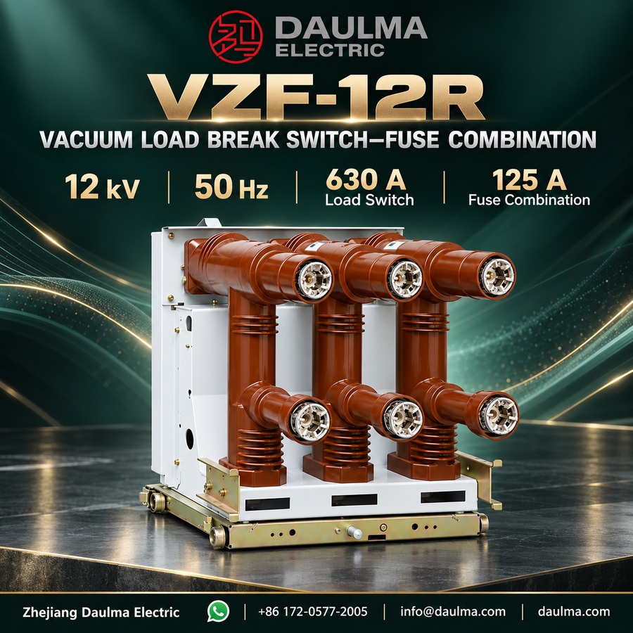
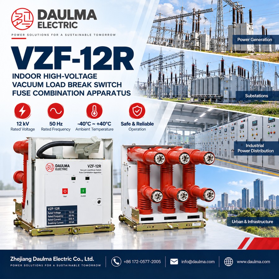
The VZF-12R is a three-phase 50 Hz indoor high voltage vacuum load break switch – fuse combination unit of centre-mounted, solid-insulated (epoxy embedded-pole) construction, designed for use as the switching and protection unit of 12 kV armoured metal-enclosed and air-insulated switchgear cubicles. It complies with GB 3804 and GB 16926 and, within the rated range, safely and reliably switches normal load current while the associated fuse clears fault current.
The unit is offered in two configurations: as a vacuum load break switch (VZF12/T630-20, 630 A rated current, 20 kA short-time withstand) for load switching and isolation, and as a load break switch – fuse combination unit (VZF-12/T125-50, 125 A fuse, 50 kA fuse breaking, 3150 A rated transfer current) where transformer and line faults are interrupted by the back-up fuse. The vacuum interrupter handles the load current, the spring operating mechanism provides stored-energy operation, and the switch and fuse are mechanically interlocked so that a fuse strike opens the corresponding switch pole.
Model Designation
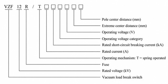
The type is designated VZF12R / T □ □ □ □ □ □ and decoded as follows:
- VZF — vacuum load break switch
- 12 — rated voltage kV
- R — with fuse (combination unit)
- T — spring operating mechanism
- □ — rated current A
- □ — rated short-circuit breaking current kA
- □ — operating-voltage category and control voltage V
- □ — pole spacing / phase spacing mm
Examples: VZF12/T630-20 denotes a 12 kV vacuum load break switch with 630 A rated current and 20 kA short-time withstand current; VZF-12/T125-50 denotes a load break switch – fuse combination unit with a 125 A fuse and 50 kA fuse breaking current.
Performance Advantages
- Solid-insulated embedded-pole design. The switch poles are encapsulated in epoxy resin (APG), giving a compact centre-mounted unit that is insensitive to dust and moisture and requires no special maintenance of the live parts.
- Vacuum interruption with spring mechanism. The load current is broken in a vacuum interrupter driven by a spring energy-storage mechanism, allowing reliable close / open / earthed operation and safe isolation for maintenance.
- Switch – fuse coordination. In the combination unit the fuse clears short-circuit faults and its striker trips the associated switch pole, with a rated transfer current of 3150 A ensuring reliable phase-by-phase fault clearance without overloading the switch.
Technical Parameters
Service Conditions
- Ambient temperature: upper +40℃, lower -40℃
- Altitude: not above 1500 m
- Relative humidity: daily average ≤ 95%, monthly average ≤ 90%
- Vapour pressure: daily average ≤ 2.2 × 10⁻³ MPa, monthly average ≤ 1.8 × 10⁻³ MPa
- Seismic intensity: not above intensity 8
- Environment: no dripping, no fire or explosion hazard, no chemical corrosive gas and no violent vibration
Main Technical Parameters
The VZF-12R is offered as a stand-alone vacuum load break switch (VZF12/T630-20) and as a load break switch – fuse combination unit (VZF-12/T125-50). The two columns below compare the two configurations.
| No. | Item | Unit | VZF12/T630-20 (vacuum load break switch) |
VZF-12/T125-50 (switch-fuse combination) |
|---|---|---|---|---|
| 1 | Rated voltage | kV | 12 | 12 |
| 2 | 1 min power-frequency withstand voltage (phase-to-phase / to earth) | kV | 42 | 42 |
| 3 | Lightning impulse withstand voltage (phase-to-phase / to earth) | kV | 75 | 75 |
| 4 | Rated current | A | 630 | 125 (fuse) |
| 5 | Rated short-circuit breaking current | kA | — | 50 (by fuse) |
| 6 | Rated short-time withstand current | kA | 20 | — |
| 7 | Rated peak withstand current | kA | 50 | — |
| 8 | Rated short-circuit making current (peak) | kA | 50 | — |
| 9 | Rated cable charging breaking current | A | 16 | — |
| 10 | Rated transfer current | A | — | 3150 |
| 11 | Breaking of no-load transformer | kVA | 1250 | — |
| 12 | Mechanical life | operations | 10000 | — |
| 13 | Partial discharge | pC | ≤ 5 | — |
Standards
- Load switch designed and tested to GB 3804 (AC high-voltage load switches)
- Switch-fuse combination designed and tested to GB 16926 (AC high-voltage load switch – fuse combination units)
Installation & Wiring
Installation and Mounting
The VZF-12R is a centre-mounted, solid-insulated switch for indoor armoured switchgear cubicles. The epoxy embedded-pole unit is fixed to the cubicle frame on the base rails; the primary terminals are connected to the busbar or cable lugs, and where fitted the fuses are inserted in the dedicated fuse compartments above the switch poles. The secondary control loop (spring motor, auxiliary and anti-pumping contacts, fuse-striker trip) is wired to the cubicle terminal block. The earth switch and the mechanism interlocks must be verified, and the frame reliably earthed, before commissioning.
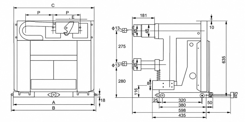
Outline and Installation Dimensions
Main outline dimensions (mm) taken from the datasheet outline drawing are summarised below; the full dimension set (A, B, C, P, E and pole/phase spacing) is given on the approved outline drawing supplied with each order.
| Outline dimension | Value (mm) |
|---|---|
| Overall height | 635 |
| Overall depth (side view) | 435 |
| Base mounting span | 320 / 380 / 598 |
| Vertical pole spacing | 275 / 280 |
| Mounting hole diameter | 4 × Ø 13 |
Applications
- 12 kV indoor armoured switchgear for ring-network and transformer-feeder protection
- Distribution boxes and substations requiring load switching with fuse back-up
- Control and protection of transformers and cable feeders switched without a dedicated circuit breaker
Selection & FAQs
Selection Guide
- Configuration. Choose the stand-alone vacuum load break switch (VZF12/T630-20) for load switching and isolation, or the load break switch – fuse combination (VZF-12/T125-50) where transformer or line faults must be cleared by the back-up fuse.
- Rated current and fuse. Match 630 A (switch) or the 125 A fuse rating to the load / transformer current, and select the fuse by voltage class, rated current, minimum breaking current and the time-current curve.
- Transfer-current coordination. Verify the 3150 A rated transfer current against the prospective fault level so that faults are reliably cleared phase-by-phase by the fuse without exceeding the switch duty.
- Withstand ratings. Check the 20 kA short-time and 50 kA peak withstand values against the system fault level; in the stand-alone switch these are withstand values, not a breaking capability.
- Service conditions. Confirm a 12 kV 50 Hz indoor system within -40℃ to +40℃, altitude ≤ 1500 m, humidity daily ≤ 95% / monthly ≤ 90% and seismic intensity ≤ 8.
- Compare neighbouring designs. For short-circuit protection with a dedicated breaker see Vacuum Circuit Breakers; for other load-switching designs see HV Load Break Switches.
FAQs
Q1: What does the type designation VZF-12R mean?
VZF denotes a vacuum load break switch, 12 the rated voltage in kV and R the fuse (combination) version; T indicates a spring operating mechanism, and the following boxes give the rated current, rated breaking current, control-voltage details and pole / phase spacing. VZF12/T630-20 is the 630 A load switch and VZF-12/T125-50 the 125 A fuse combination unit.
Q2: What is the difference between a load break switch-fuse combination and a circuit breaker?
The load break switch makes and breaks normal load current and provides isolation, while short-circuit faults are cleared by the back-up fuse in the combination unit. A circuit breaker interrupts both load and short-circuit current with its own mechanism. Choose the switch-fuse combination for economical transformer-feeder protection and a circuit breaker where repeated short-circuit interruption is required.
Q3: What is the rated transfer current and why does it matter?
The rated transfer current (3150 A) is the current range over which the fault duty is reliably transferred from the switching device to the fuse so that the fuse clears the fault. It ensures that, during the switch-fuse operating time, the combination interrupts the fault correctly without the switch exceeding its capability.
Q4: What are the insulation levels of the VZF-12R?
For the 12 kV class the 1 min power-frequency withstand voltage is 42 kV and the lightning impulse withstand voltage is 75 kV (phase-to-phase and phase-to-earth), with partial discharge not exceeding 5 pC.
Q5: What are the service conditions?
Ambient temperature -40℃ to +40℃, altitude not above 1500 m, relative humidity daily average ≤ 95% and monthly average ≤ 90%, seismic intensity not above 8, and an environment free from dripping, fire, explosion, corrosive gas and violent vibration.
Q6: What data do I need to provide when ordering?
Please state the configuration (load switch or switch-fuse combination), rated voltage, rated current or fuse rating, control / operating voltage and category, required pole and phase spacing, the prospective fault level for transfer-current coordination, and any special service conditions.