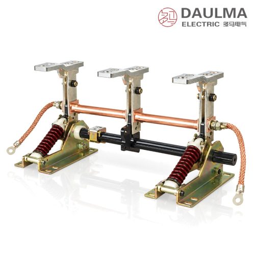
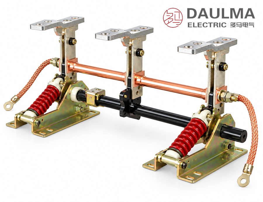
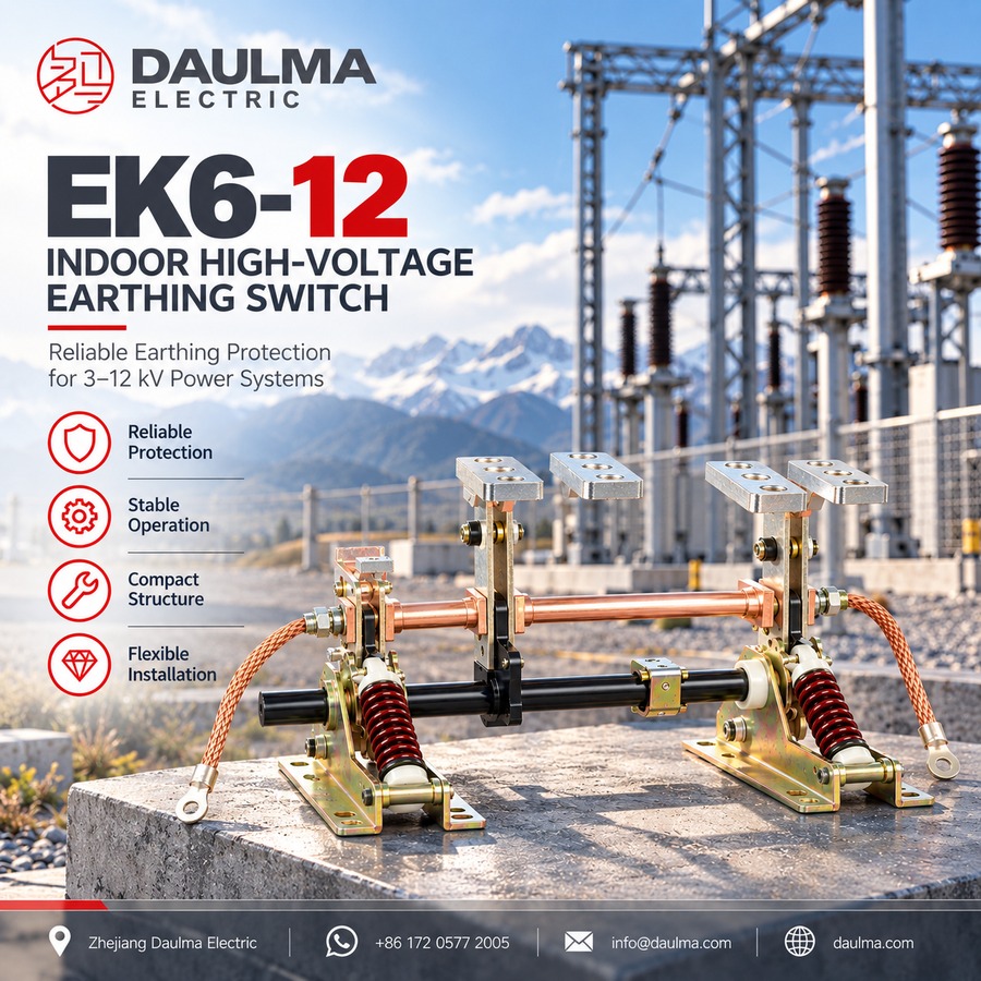
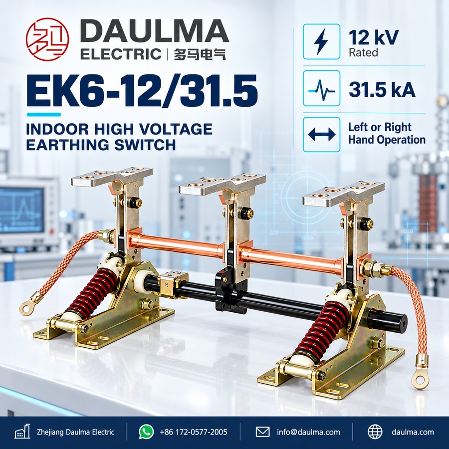
The EK6-12/31.5 is an indoor high voltage earthing switch for three-phase 50 Hz systems of 3 kV to 12 kV, rated 12 kV with a rated short-time withstand current of 31.5 kA. It is fitted inside a metal-enclosed switchgear cubicle and bonds a de-energised circuit to the earthing network, protecting maintenance work against accidental re-energising. The performance conforms to GB 1985 for AC high-voltage disconnectors and earthing switches and to IEC 129.
The switch earths only: it is closed after the circuit has been isolated and proved de-energised, and it interrupts neither load nor short-circuit current. Five frames are tabulated with phase-centre distances of 150, 210, 230, 250 and 275 mm, covering the busbar spacings met in cubicles of different makers. The catalogue carries no rated-parameter table, so the remaining ratings are fixed by the technical agreement and stated on the nameplate.
Model Designation
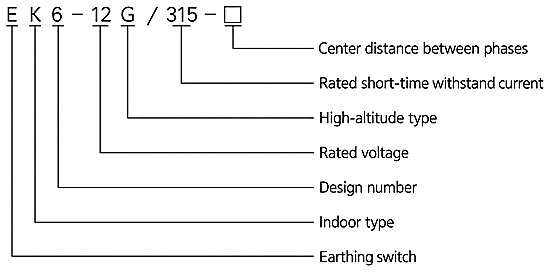
The type is designated E K 6 – 12 G / 315 – □ and decoded as follows:
- E — earthing switch
- K — indoor installation
- 6 — design sequence number
- 12 — rated voltage, kV
- G — high-altitude version
- 315 — rated short-time withstand current, kA
- □ — phase-centre distance, mm
The designation chart prints the short-time withstand figure as 315 while the product heading and the dimension table use 31.5; both refer to the same 31.5 kA and that is the figure used throughout this page. The five tabulated frames are EK6-12/31.5-150, EK6-12/31.5-210, EK6-12/31.5-230, EK6-12/31.5-250 and EK6-12/31.5-275, where the last field is the phase-centre distance in mm; the high-altitude G version shares the same drawing but is not one of the five tabulated frames.
Construction and Operation
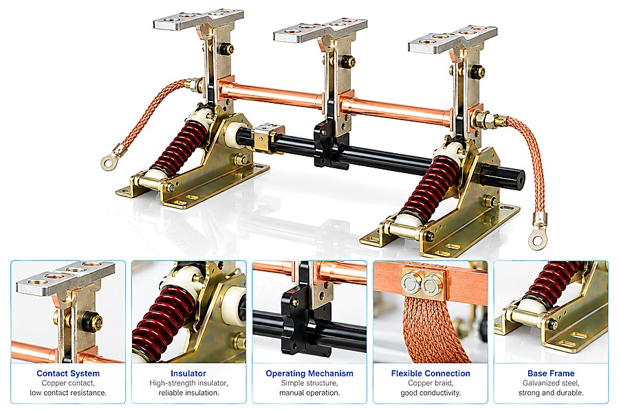
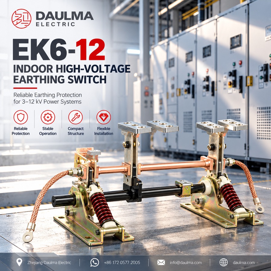
The switch is built as three earthing poles on a galvanized steel base frame, each pole carrying a rotating earthing knife on a high-strength support insulator with copper contacts. The three knives are coupled to one operating shaft driven by a simple manual mechanism, so one stroke closes or opens all three poles together, and the mechanism is assembled for left-hand or right-hand operation. Flexible copper braid connections link the earth circuit to each pole, and the switch carries and closes against the short-time withstand current without any interrupting capability.
Technical Parameters
Standards and Rated Values
The performance of the series conforms to GB 1985 for AC high-voltage disconnectors and earthing switches and to IEC 129. The switch is applied in indoor power systems of 3 kV to 12 kV at 50 Hz, with a rated voltage of 12 kV and a rated short-time withstand current of 31.5 kA.
Normal Service Conditions
- Ambient air temperature: upper limit +40℃, lower limit −10℃.
- Storage and transport are permitted down to −30℃.
- Altitude: not exceeding 1000 m.
- Seismic intensity: not above 8.
- The site is free from flammable or explosive hazards, from severe dust and chemical corrosion and from violent vibration.
Installation & Wiring
Installation and Mounting
Fix the frame to the cubicle structure through the slotted mounting holes, set the poles to the phase-centre distance of the busbar in use, and bond the frame to the cubicle earth circuit. Couple the operating shaft to the mechanism on the side the panel allows, then operate the switch by hand and check that every pole reaches the full closed position and the knives seat on their contacts. Bolt the copper terminal plate of the earthed circuit to the terminals and verify the interlock with the associated isolating switch or circuit breaker before the switch is returned to service.
Outline and Installation Dimensions
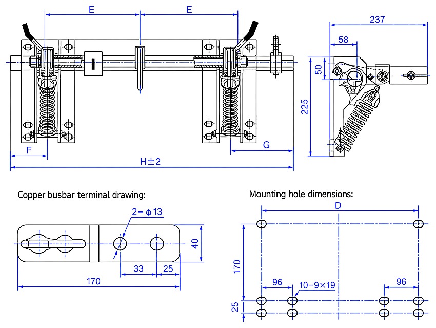
Dimensions in mm, from the outline drawing. In the front view E is the distance between adjacent pole centre lines and is marked twice; F and G are the offsets from the frame ends to the outer pole centre lines; H is the overall width, drawn as H ± 2 mm, and the tabulated values satisfy H = F + 2E + G. The side view gives a depth of 237 and a height of 225, with 58 and 50 at the top.
| Model | E | F | G | H | D |
|---|---|---|---|---|---|
| EK6-12/31.5-150 | 150 | 75 | 160 | 535 | 396 |
| EK6-12/31.5-210 | 210 | 50 | 185 | 655 | 516 |
| EK6-12/31.5-230 | 230 | 50 | 185 | 695 | 556 |
| EK6-12/31.5-250 | 250 | 50 | 185 | 735 | 596 |
| EK6-12/31.5-275 | 275 | 50 | 210 | 810 | 646 |
Copper busbar terminal: the plate measures 170 by 40, with two Ø13 holes on the centre line 33 apart and the outer hole 25 in from the plate end.
Mounting holes: ten slots of 9 × 19 mm — two upper slots at the transverse distance D, and below them two groups of four, each group 170 below the upper slot with its rows 25 apart and its inner column 96 from the upper slot centre line. D equals twice the phase-centre distance plus 96.
Selection & FAQs
Selection Guide
- Take the phase-centre distance from the busbar or the cable routing of the cubicle; the five frames cover 150, 210, 230, 250 and 275 mm.
- Check the overall width H and the mounting-hole width D against the panel before ordering, since both grow with the phase-centre distance.
- State left-hand or right-hand operation of the mechanism to match the handle position available on the cubicle front.
- Order the G version when the switch is installed above 1000 m; the standard frames are rated for altitudes up to 1000 m.
- An earthing switch does not isolate. Pair it with a disconnector or a circuit breaker that provides the visible break, as on our GN24-12D disconnector with earthing switch.
- For the wider switchgear range see the indoor and outdoor disconnectors category.
Frequently Asked Questions
Q1: What does the type designation EK6-12/31.5 mean?
E is the earthing switch and K the indoor installation, 6 is the design sequence number and 12 the rated voltage in kV. An optional G marks the high-altitude version, the figure after the slash is the rated short-time withstand current in kA, printed 315 on the chart and 31.5 in the heading, and the last field is the phase-centre distance in mm.
Q2: What does an earthing switch do?
After the circuit has been isolated and proved de-energised, the closed earthing knife bonds that circuit to the earthing network of the cubicle. This holds the equipment at earth potential while it is worked on and protects the maintenance staff against accidental re-energising or induced voltage.
Q3: How is the phase-centre distance chosen?
Five frames are tabulated, 150, 210, 230, 250 and 275 mm. The distance is set by the busbar spacing or the cable routing of the cubicle, and the overall width and the mounting cut-out grow with it, from H 535 mm with D 396 mm at the smallest frame to H 810 mm with D 646 mm at the largest.
Q4: Can this switch interrupt load or short-circuit current?
No. It is an earthing switch: it carries and closes against the short-time withstand current but has no interrupting capability. It may be operated only after the associated circuit breaker or disconnector has opened the circuit, and the two are interlocked so that the earthing knife cannot close on a live circuit.
Q5: What is the G version and what are the electrical ratings?
G is the high-altitude version of the same frame; the standard switch is rated for altitudes up to 1000 m. The rated short-time withstand current is 31.5 kA. The catalogue page carries no rated-parameter table, so the rated current, the peak withstand current, the short-circuit duration and the insulation level are fixed by the technical agreement and are given on the nameplate.
Q6: What must be stated when ordering, and what service conditions apply?
State the model, the rated voltage, the phase spacing, the mounting position and whether the mechanism is to be operated from the left or from the right; special requirements are settled with the factory. Service conditions are ambient air temperature from −10℃ to +40℃, storage and transport down to −30℃, altitude not above 1000 m, seismic intensity not above 8, and a site free from flammable or explosive hazards, severe dust, chemical corrosion and violent vibration. The series is listed under high-voltage earthing switches.