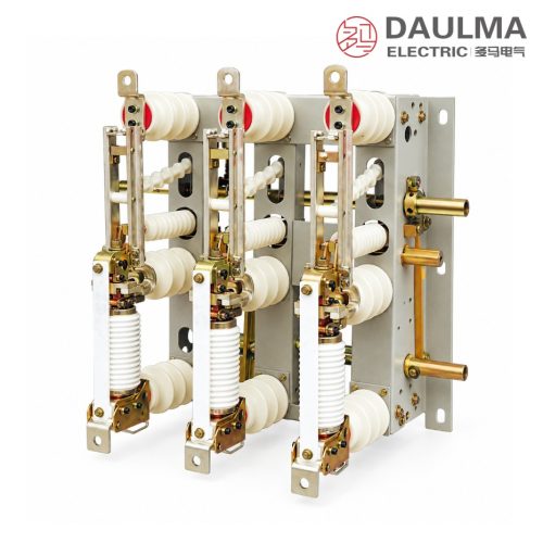
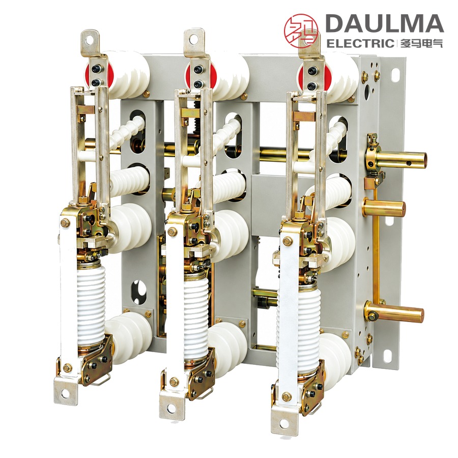
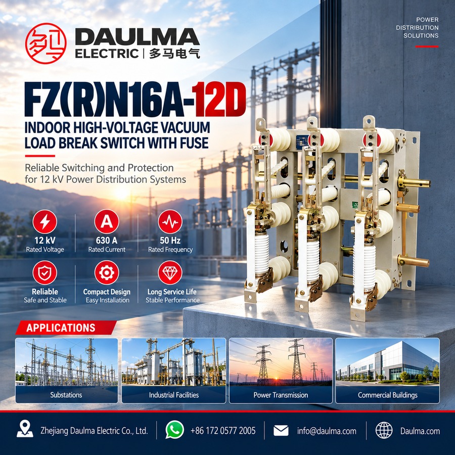
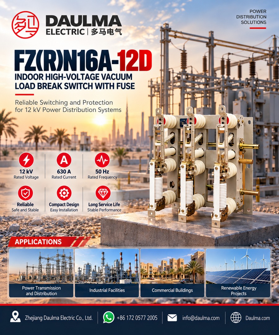
The FZN16A-12D indoor high-voltage vacuum load break switch and the FZRN16A-12D switch-fuse combination unit are three-phase switching units for distribution networks of 6 to 12 kV at 50 Hz. They control and protect transformers, cables and line sections, and are used in switch stations, distribution rooms, and industrial and commercial substations.
The load break switch makes and breaks load current. In the combination unit the circuit is completed with back-up fuses, so the switch breaks load current and overload current while the fuse clears short-circuit current. The combination unit also protects the transformer against overload and keeps the equipment from running on two phases after a fuse blows.
The unit suits installations that call for an oil-free switch, no overhaul between services and frequent operation. It can be worked by a CS6-1 mechanism or directly on the switch frame without an additional mechanism, and the FZN16A-12-J version provides motor operation with manual back-up for remote control.
Model Designation
Two designations are used, one for the switch and one for the combination unit:
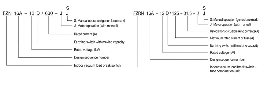
Load break switch — FZN16A-12D/630
- FZN: indoor vacuum load break switch
- 16: design sequence number
- A: derivative code
- 12: rated voltage, kV (the unit serves distribution networks of 6 to 12 kV)
- D: earthing switch with making capacity
- 630: rated current, A
- J: motor operation, with manual operation
- S: manual operation, generally no mark
Switch-fuse combination unit — FZRN16A-12D/125-31.5
- FZRN: indoor vacuum load break switch combined with fuse
- 125: maximum rated current of the fuse, A
- 31.5: rated short-circuit breaking current, kA
The remaining codes carry the same meaning as in the switch designation. The first 16 is the design sequence number and the 12 after it is the rated voltage in kV.
Construction and Design
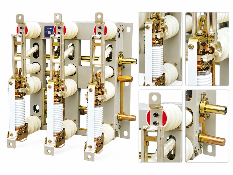
The vacuum arc extinction chambers of the three poles stand upright on a common steel frame carried on insulating support columns, which keeps the unit compact and gives it high dynamic and thermal stability. Insulating pull rods and sliders transmit the movement of the mechanism to the contacts, so each closing or opening operation is completed in one stroke and the contact speed is independent of the operator.
The switch has a visible isolation gap, and the earthing switch with making capacity bonds the de-energised side before maintenance. Mechanical interlocks between the load break switch, the earthing switch and the fuse compartment satisfy the five-prevention requirements of switchgear.
Operating Mechanism and Control
The spring mechanism is charged for closing, and a buffer pad absorbs the impact at opening while an auxiliary switch serves the control and signalling circuits. The vacuum chamber holds its contacts over a long electrical life, so the unit is offered for networks that switch often and for panels that are not opened for maintenance between services.
Motor operation with an electric motor and a release device is available, which allows the unit to take part in remote control and to trip on a protective relay signal. The fuse compartment of the combination unit is interlocked so that a fuse cannot be reached while the circuit is live.
Technical Parameters
Service Conditions
- Ambient temperature: +40℃ upper, -25℃ lower
- Altitude: Not more than 1000 m
- Relative humidity: Daily average not more than 95%, monthly average not more than 90%
- Seismic intensity: Not more than 8 degrees
- Site condition: No fire, explosion hazard, chemical corrosion or violent vibration
- Pollution level: II
Technical Data
| No. | Item | Unit | Value |
|---|---|---|---|
| 1 | Rated voltage / highest operating voltage | kV | 12 |
| 2 | Rated frequency | Hz | 50 |
| 3 | Rated current | A | 630 |
| 4 | Rated breaking current of active load | A | 630 |
| 5 | Rated closed-loop breaking current | A | 630 |
| 6 | Rated breaking current of 5% active load | A | 31.5 |
| 7 | Rated cable charging breaking current | A | 10 |
| 8 | Rated capacitive breaking current | A | 400 |
| 9 | Rated no-load transformer breaking current | A | No-load current of a 1600 kVA transformer |
| 10 | 1 min power-frequency withstand voltage (finite value), to earth and between phases / across the isolation gap | kV | 42/48 |
| 11 | Lightning impulse withstand voltage, full wave (peak), to earth and between phases / across the isolation gap | kV | 75/85 |
| 12 | Rated short-time withstand current (thermal stability) | kA/S | 20/3 |
| 13 | Rated peak withstand current (dynamic stability) | kA | 50 |
| 14 | Rated short-circuit making current | kA | 50 |
| 15 | Number of breaking operations at rated current | times | 10000 |
| 16 | Mechanical life | times | 10000 |
| 17 | Permissible cumulative wear of the contacts | mm | 3 |
| 18 | Operating torque for opening and closing | N.m/(N) | 120 (240) |
| 19 | Rated closing operating voltage / current | V/A | ~220/0.5 |
| 20 | Rated opening operating voltage / current | V/A | ~220/3 |
Installation & Wiring
Installation and Commissioning
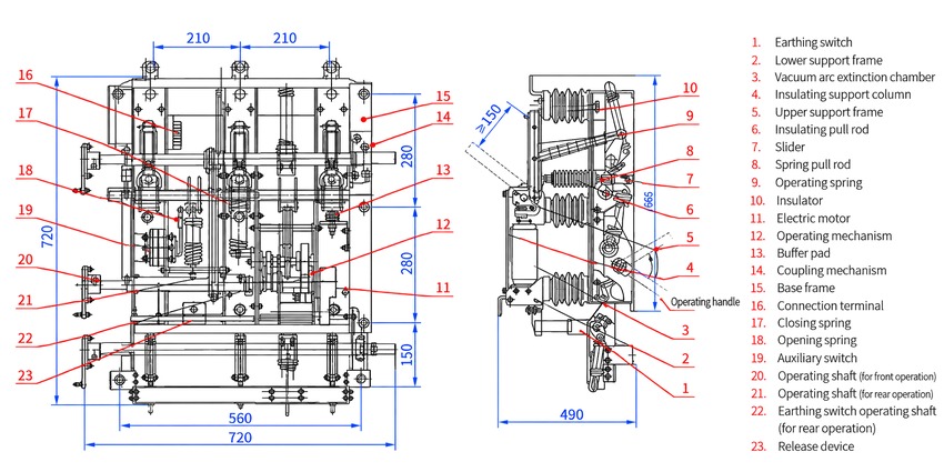
- Frame mounting: the three-pole unit is bolted to the cubicle frame with 210 mm between adjacent poles; check the busbar and cable clearances and the drilling against the approved outline drawing before the frame is torqued.
- Operation arrangement: the drawing shows an operating shaft for front operation and separate shafts for rear operation of the switch and of the earthing switch; confirm which arrangement the panel needs before ordering, as the shaft positions differ.
- Mechanism checks: charge the closing spring, confirm the closed, open and earthed positions on all three poles, verify the coupling mechanism and the interlocking between load break switch, earthing switch and fuse compartment, and check the position indication and the auxiliary switch contacts.
- Fuse loading (combination unit): fit the specified back-up fuse of up to 125 A, confirm that the striker engages the release device, and check the fuse rating against the tabulated 31.5 kA breaking capability.
Outline Dimensions
- Phase spacing: 210 mm between adjacent poles, marked twice on the front view
- Front view, horizontal: 560 mm and 720 mm, with 720 mm outermost
- Front view, vertical: 280 mm, 280 mm and 150 mm in three steps
- Side view: 490 mm horizontal and 665 mm vertical
- Marked diagonal dimension: not less than 150 mm
- Panel details: the outline drawing carries the complete dimension set; request the drawing for panel cut-outs and busbar drilling
Component Reference
The item numbers below follow the outline and installation drawing of the series:
- Earthing switch
- Lower support frame
- Vacuum arc extinction chamber
- Insulating support column
- Upper support frame
- Insulating pull rod
- Slider
- Spring pull rod
- Operating spring
- Insulator
- Electric motor
- Operating mechanism
- Buffer pad
- Coupling mechanism
- Base frame
- Connection terminal
- Closing spring
- Opening spring
- Auxiliary switch
- Operating shaft (for front operation)
- Operating shaft (for rear operation)
- Earthing switch operating shaft (for rear operation)
- Release device
Applications
- Switch stations and distribution rooms of 6 to 12 kV
- Industrial and commercial substations with frequent switching
- Transformer feeders protected by the switch-fuse combination unit
- Oil-free units that are not opened for overhaul between services
Selection & FAQs
Selection Guide
- Choose the switch or the combination unit. The FZN16A-12D/630 carries load current only and relies on upstream protection; transformer feeders normally take the FZRN16A-12D/125-31.5 unit, where the back-up fuse clears the fault and the loss of a phase is signalled by the mechanism.
- Match the fuse to the transformer. The combination unit is drawn with a back-up fuse of up to 125 A and a rated short-circuit breaking current of 31.5 kA, and the chamber breaks the no-load current of a 1600 kVA transformer, so check the magnetising inrush of the transformer against that fuse rating.
- Check the short-time duty. 20 kA for 3 s with a 50 kA peak withstand and a 50 kA short-circuit making current set the busbar and upstream protection coordination; verify these against the network before ordering.
- Confirm the breaking duties the application needs. The tabulated family of breaking currents covers closed-loop switching, 5% active load, cable charging at 10 A, capacitive current at 400 A and no-load transformer current, which is what distinguishes a unit built for frequent operation from a simple isolator.
- Select the operation and the panel arrangement. Manual operation with a CS6-1 mechanism or direct operation is standard, the J version adds motor operation for remote control, and the drawing offers front operation or rear operation for the switch and the earthing switch.
FAQs
Q1: What is the FZN16A-12D used for?
It is an indoor three-phase vacuum load break switch for distribution networks of 6 to 12 kV at 50 Hz, used to make and break load current, to isolate the circuit through a visible gap and to earth the de-energised side for maintenance. The FZRN16A-12D combination unit adds back-up fuses so the same frame also clears short-circuit current and protects a transformer.
Q2: How do I read FZRN16A-12D/125-31.5?
FZN = indoor vacuum load break switch, R = combined with fuse, 16 = design sequence number, A = derivative code, 12 = rated voltage in kV, D = earthing switch with making capacity, 125 = maximum rated current of the fuse in A, and 31.5 = rated short-circuit breaking current in kA. The trailing letter gives the operating mode, J for motor operation with manual back-up and S for manual operation, which is generally left unmarked. Without the R the designation FZN16A-12D/630 describes the plain switch at 630 A.
Q3: Which currents can this series break?
The vacuum chamber is rated for 630 A of active load and 630 A closed-loop breaking, 31.5 A at 5% of rated active load, 10 A of cable charging current, 400 A of capacitive current and the no-load current of a 1600 kVA transformer. Short-circuit current is cleared by the back-up fuse of the combination unit at up to 31.5 kA, not by the switch alone.
Q4: How does it compare with the FZN25-12DG vacuum load break switch?
Both are indoor 12 kV vacuum units with a back-up fuse option. The FZN25-12DG is the later design rated 25 kA and offered up to 1250 A with a 200 A fuse as the main choice, and it carries a stated transfer current of 3150 A. This FZN16A-12D is rated 630 A with 20 kA for 3 s and a 50 kA peak withstand, and its data sheet gives the full family of breaking currents, so it suits panels built around a 630 A frame. Choose the FZN25-12DG where the higher short-time rating or a larger current frame is needed.
Q5: How does the vacuum design compare with SF6 and air-puff switches?
The three media differ in the interrupting chamber, not in the switching duty. The FZN16A-12D interrupts in a sealed vacuum chamber, so the contacts are protected from the arc and the unit is offered for frequent operation without overhaul. The FLN36-12 seals a low-pressure SF6 three-position interrupter for compact panels, and the FKN12A-12D blows air over the arc in an open frame with static contact covers. For overhead line duty outdoors, the FZW32-12 is the pole-mounted vacuum equivalent.
Q6: Can the unit be operated remotely, and how is it maintained?
Yes. The J version adds an electric motor and a release device, so the switch can be charged and operated from the control supply and tripped by a protective relay, while manual operation on the frame or with a CS6-1 mechanism stays available if the control supply is lost. Maintenance covers the mechanism only: keep the shafts and interlocks clean and lubricated, check the operating torque against the data sheet, and replace the vacuum chamber when the contact wear reaches the tabulated cumulative 3 mm.