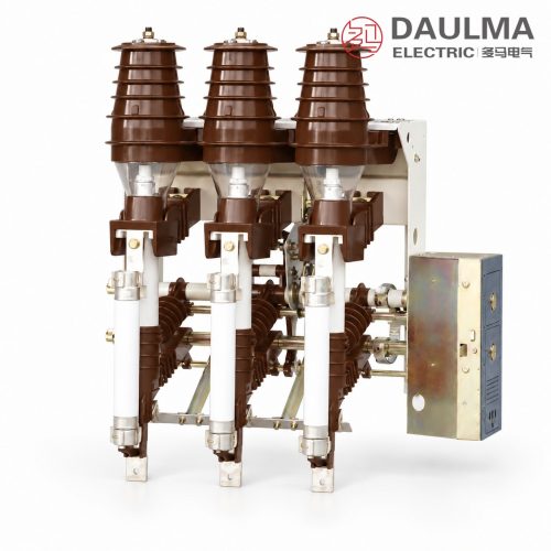
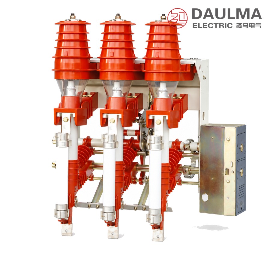
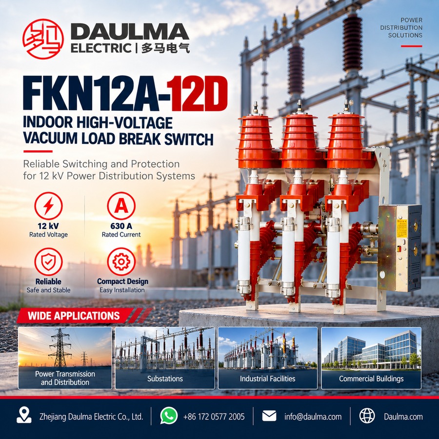
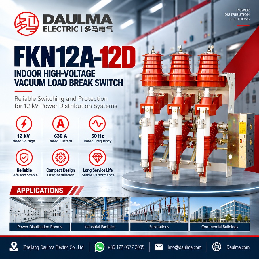
The FKN12A-12D indoor air-puff load break switch and the FKRN12A-12D switch-fuse combination unit are three-phase switching units for distribution systems of 12 kV and below. They control and protect transformers, cables and overhead line sections, and are used mainly in urban and rural terminal substations, box substations, and ring-network or double-radial supply units.
The load break switch makes and breaks load current and overload current. In the combination unit the circuit is completed with back-up fuses, so line short-circuit current is cleared as well. Switch, earthing switch, fuses and mechanism are carried on a single frame.
Model Designation
Two designations are used, one for the switch and one for the combination unit:
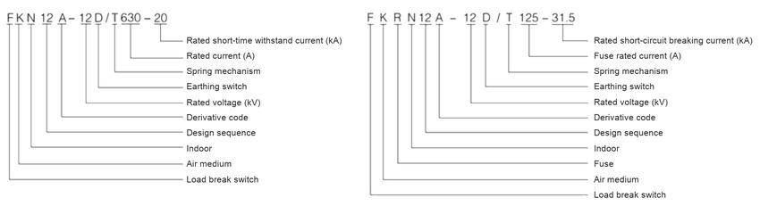
Load break switch — FKN12A-12D/T 630-20
- F: load break switch
- K: air medium, air-puff design
- N: indoor type
- 12: design sequence number
- A: derivative code
- 12: rated voltage, kV
- D: with earthing switch
- T: spring mechanism
- 630: rated current, A
- 20: rated short-time withstand current, kA
Switch-fuse combination unit — FKRN12A-12D/T 125-31.5
- R: combined with fuse
- 125: rated current of the fuse, A
- 31.5: rated short-circuit breaking current, kA
The first 12 in the designation is the design sequence number and the second is the rated voltage in kV. The letter after the voltage indicates the added earthing switch, and the letter after the slash the operating mechanism.
Construction and Design
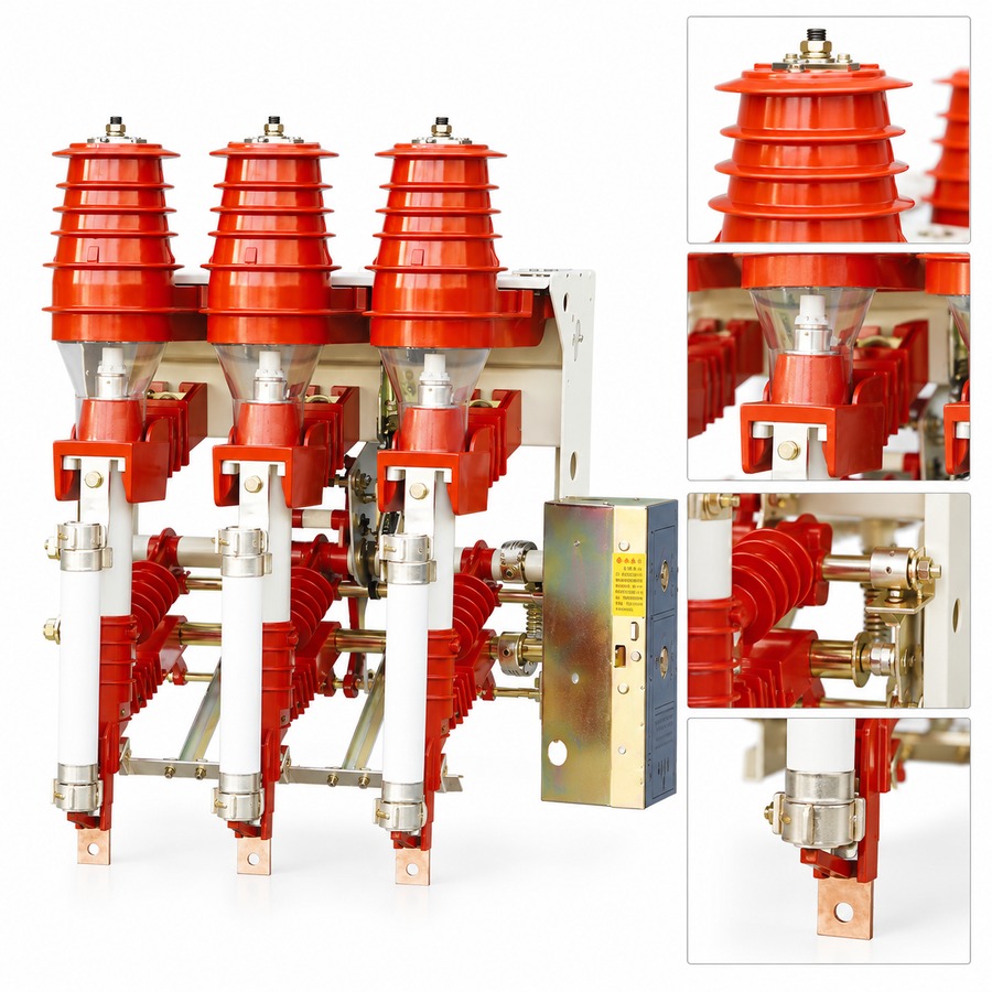
Load break switch, earthing switch, fuses and mechanism are mounted on one frame, which can be combined flexibly and keeps the unit compact and easy to install. The break is arranged upright, so the dynamic and thermal stability ratings are high and each operation is completed in one stroke. Static contact covers provide structural isolation inside the ring-main cubicle, which removes the need for inter-phase insulation boards and gap insulation plates and helps resist internal arcing faults.
Operating Function and Application
After the load break switch opens, a shutter closes automatically over the open gap, improving protection for personnel working on the panel. Reliable mechanical interlocks between the load break switch, the earthing switch and the fuses satisfy the five-prevention requirements of switchgear. Manual operation and motorised operation with an AC or DC control supply are both available, which suits the remote control and telemetry arrangements of unattended substations.
Technical Parameters
Service Conditions
- Ambient temperature: +40℃ upper, -25℃ lower
- Altitude: Not more than 1000 m
- Relative humidity: Daily average not more than 95%, monthly average not more than 90%
- Seismic intensity: Not more than 8 degrees
- Site condition: No fire, explosion hazard, chemical corrosion or violent vibration
- Pollution level: II
Technical Data
| No. | Item | Unit | Value |
|---|---|---|---|
| 1 | Rated voltage | kV | 12 |
| 2 | Rated current of the load break switch | A | 630 |
| 3 | Rated short-time withstand current | kA | 20 |
| 4 | Rated current of the fuse, combination unit | A | 125 |
| 5 | Rated short-circuit breaking current, combination unit | kA | 31.5 |
| 6 | Overall width | mm | 868 |
| 7 | Overall height | mm | 940 |
| 8 | Mass | kg | 70 |
Installation & Wiring
Installation and Commissioning
- Panel mounting: the three-pole unit is bolted into the cubicle frame across an overall width of 868 mm with an overall height of 940 mm and a mass of 70 kg; check busbar and cable clearances against the approved outline drawing before the frame is torqued.
- Operation arrangement: the outline drawing shows the two arrangements offered, side installation with right-hand operation and side installation with left-hand operation; confirm which one the cubicle needs before ordering, as the mechanism and terminal positions differ.
- Mechanism checks: charge the spring, confirm the closed, open and earthed positions on all three poles, verify the interlocking between load break switch, earthing switch and fuse compartment, and check the position indication.
- Fuse loading (combination unit): fit the specified 125 A back-up fuse, confirm the striker engagement, and verify that the fuse rating matches the tabulated 31.5 kA breaking capability.
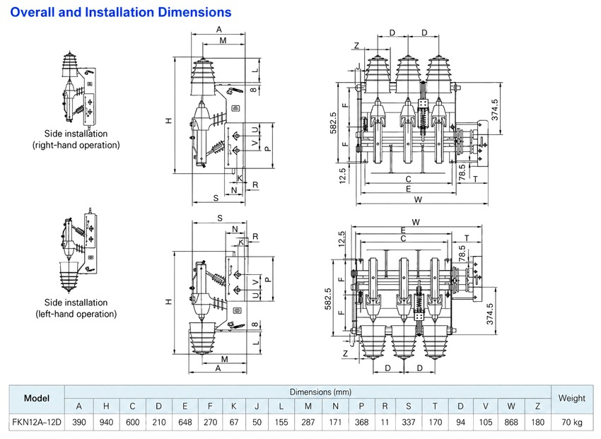
Outline Dimensions
- Overall width (W): 868 mm across the three poles
- Overall height (H): 940 mm including the live-part covers
- Phase spacing (D): 210 mm between adjacent poles
- Mass: 70 kg for the assembled three-pole unit
- Panel details: the outline drawing carries the full lettered dimension set for both operation arrangements; request the drawing for cubicle cut-outs and busbar drilling
Applications
- Urban and rural terminal substations and box substations
- Ring-network and double-radial supply units
- Transformer feeders protected by the switch-fuse combination unit
- Cable and overhead line sectionalizing in 12 kV indoor switchgear
Selection & FAQs
Selection Guide
- Choose the switch or the combination unit. The FKN12A-12D carries load and overload current only; transformer feeders normally take the FKRN12A-12D unit, where the back-up fuse clears the fault.
- Match the fuse to the transformer. The combination unit is drawn with a 125 A fuse and a 31.5 kA rated short-circuit breaking current, so check the magnetising inrush of the transformer against that fuse rating.
- Confirm the earthing switch. The D in the designation adds the earthing switch that bonds the de-energised side; keep it where the unit is the visible break point of the cubicle.
- Select the operating mode. Manual operation is standard, and motorised operation with an AC or DC control supply is available where the panel takes part in remote control and telemetry.
- Check the cubicle against the outline drawing. The 868 mm width, 940 mm height, 210 mm phase spacing and 70 kg mass must fit the bay, and the chosen operation arrangement must leave the mechanism accessible.
FAQs
Q1: What is the FKN12A-12D used for?
It is an indoor three-phase 12 kV air-puff load break switch for switchgear cubicles, used to make and break load current and overload current, to isolate the circuit and to earth the de-energised side for maintenance. It controls and protects transformers, cables and overhead line sections in urban and rural terminal substations, box substations and ring-network units.
Q2: How do I read FKRN12A-12D/T 125-31.5?
F = load break switch, K = air medium, R = combined with fuse, N = indoor type, first 12 = design sequence number, A = derivative code, second 12 = rated voltage in kV, D = with earthing switch, T = spring mechanism, 125 = rated current of the fuse in A, and 31.5 = rated short-circuit breaking current in kA. Without the R the designation FKN12A-12D/T 630-20 describes the plain switch at 630 A with 20 kA short-time withstand.
Q3: What is the difference between the switch and the combination unit?
The FKN12A-12D switches load and overload current, and depends on upstream protection for faults. The FKRN12A-12D adds back-up fuses in the same frame, so a line short-circuit fault is cleared by the fuse at up to 31.5 kA and the switch then isolates the healthy circuit.
Q4: Can the FKN12A-12D interrupt short-circuit current?
No. The load break switch withstands 20 kA short-time but its chamber is designed for load, overload and closing or opening operations, not for fault interruption. Short-circuit interruption belongs to the fuse of the combination unit, and fitting a fuse of another rating changes that capability.
Q5: How does it compare with the FN5-12 (RDL) load break switch?
Both are indoor 12 kV air-puff units with back-up fuses for ring-main and transformer duty, and both are rated 630 A with 20 kA short-time withstand. The FN5-12 (RDL) is the three-position switch with a transfer current of 1.3 kA for fuse coordination, while this FKN12A-12D series is the A derivative with an added earthing switch, static contact covers that remove inter-phase insulation boards, and an automatic shutter over the open gap. Choose the FN5-12 (RDL) for a proven ring-main unit and the FKN12A-12D where the earthing switch and cover-shutter insulation are required.
Q6: How does the air-puff design compare with SF6 and vacuum switches?
The three media differ in the interrupting chamber, not in the switching duty. The FKN12A-12D blows air over the arc in an open indoor frame; the FLN36-12 seals a low-pressure SF6 three-position interrupter, which suits frequent operation and compact panels; and the FZN25-12DG interrupts in a vacuum chamber and is offered up to 1250 A. For overhead line duty outdoors, the FZW32-12 is the pole-mounted equivalent.