Overview
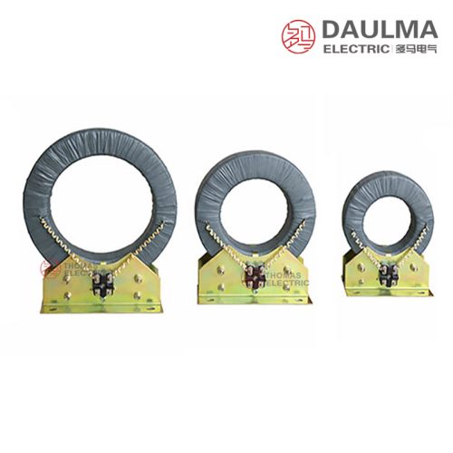
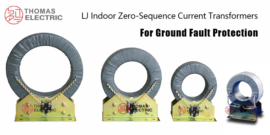
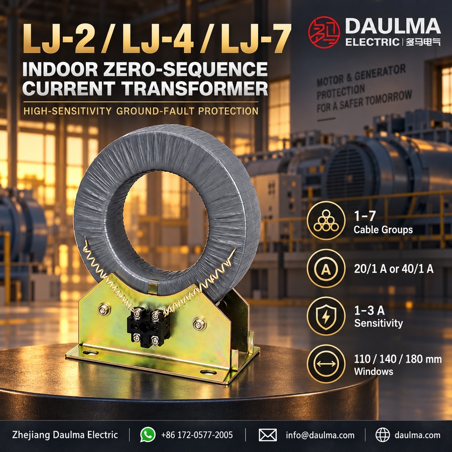
The LJ-2, LJ-4, and LJ-7 are indoor-type zero-sequence current transformers designed for ground fault protection in low-current grounding systems. They are suitable for AC 50/60 Hz networks typically up to 35 kV class, with primary insulation provided by the cable jacket and secondary winding insulation rated for 3 kV power frequency withstand voltage.
These cast-resin insulated devices offer high sensitivity for residual current detection and are commonly used with DD-11/60 or equivalent ground fault relays. Applications include protection of generators, motors, synchronous condensers, and cable feeders in industrial and utility power systems, complying with standard practices for ground fault protection in medium-voltage installations.
Key Ratings Snapshot
| Parameter | Rating |
|---|---|
| Application | Residual (zero-sequence) current detection |
| System frequency | 50/60 Hz |
| Installation environment | Indoor only |
| Typical system voltage | ≤35 kV (project-dependent) |
| Protected equipment | Generators, motors, synchronous condensers, cable feeders |
| Secondary insulation | 3 kV power frequency withstand (1 min) |
| Primary conductor | Cable passing through core (no electrical connection) |
| Secondary output | Proportional to residual current |
| Typical relay pairing | DD-11/60 or equivalent |
| Core type | Toroidal, high-permeability magnetic material |
| Supported cable OD | ≤50 mm |
| Operating principle | Electromagnetic induction |
Model Designation
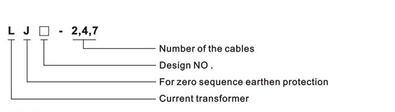
- L: Current transformer (CT)
- J: Zero-sequence / ground fault protection application
- 2 / 4 / 7: Number of cables supported (typical application reference)
Construction
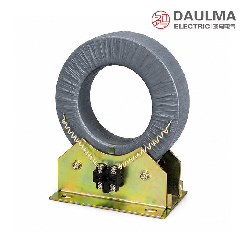
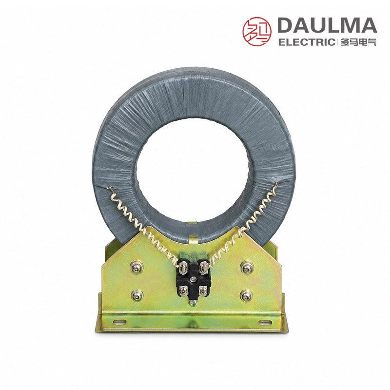
The LJ series features a ring-type toroidal core made of high-permeability magnetic material to ensure uniform flux distribution and high sensitivity. The secondary winding is evenly distributed around the core to provide stable output characteristics. Primary insulation is supplied by the cable jacket, while the secondary winding is insulated to withstand 3 kV power frequency voltage to ground for one minute. Mechanical mounting is achieved via a bracket with pre-positioned holes, enabling secure and rapid installation in indoor switchgear panels, control rooms, or cable trenches. Secondary terminals are clearly marked for correct polarity and reliable connection to ground fault relays.
Technical Parameters
Service Conditions
- Installation environment: Indoor installation only
- Rated frequency: 50 Hz or 60 Hz
- Altitude: Not exceeding 1000 m above sea level (higher altitude requires engineering confirmation)
- Ambient temperature: −5 °C to +40 °C
- Relative humidity: High-humidity indoor environments are acceptable provided no condensation occurs on live parts
- Environmental conditions: Free from corrosive gases, explosive or flammable media, severe vibration, mechanical shock, or impact
Technical Parameters
The LJ-2, LJ-4, and LJ-7 are indoor cast-resin zero-sequence current transformers designed for ground fault protection in 50/60 Hz systems. They operate within an ambient temperature range of −5 °C to +40 °C and at altitudes up to 1000 m, with a typical rated current ratio range of 20/1 to 40/1 A.
Electrical Parameters (Relay-Oriented)
| Model | Cable Capacity |
Secondary Loop Resistance |
Adjustment / Setting Current |
Sensitivity | Rated Current Ratio |
|---|---|---|---|---|---|
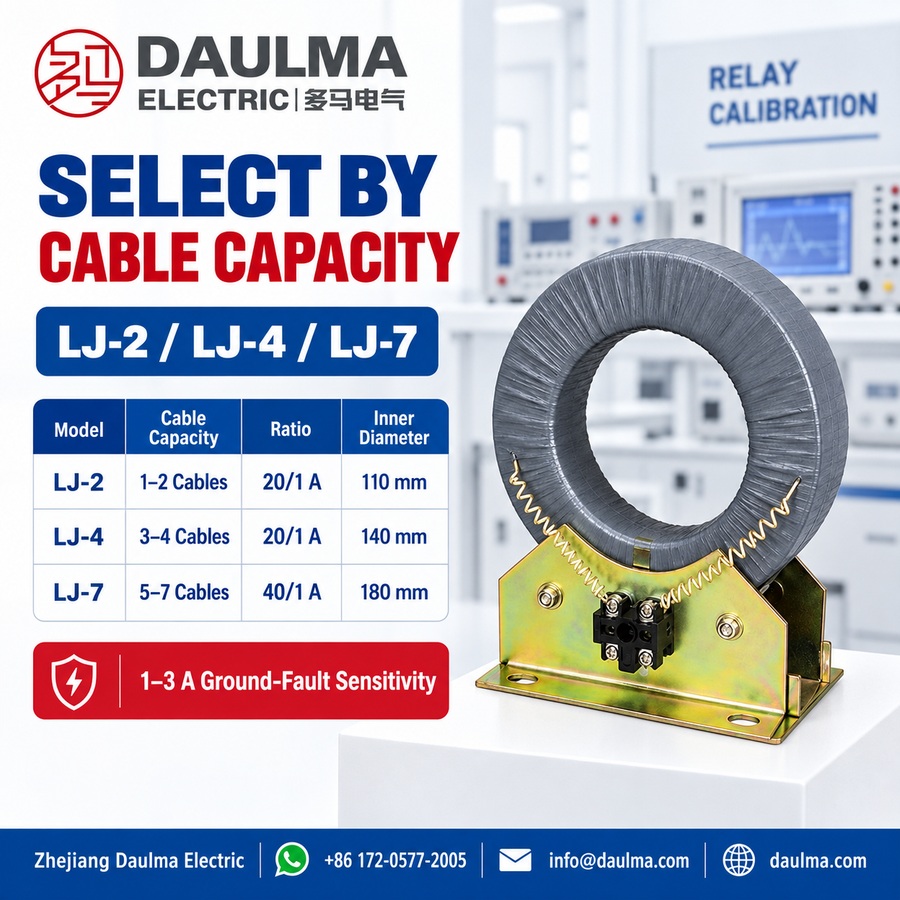
| LJ-2 | 1–2 | 10 Ω | 0.03 A | 1–3 A | 20/1 A |
| LJ-4 | 3–4 | 10 Ω | 0.03 A | 1–3 A | 20/1 A |
| LJ-7 | 5–7 | 10 Ω | 0.03 A | 1–3 A | 40/1 A |
Installation & Wiring
Installation Diagram
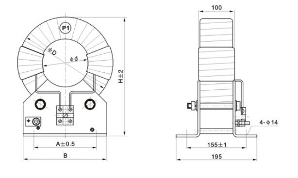
Dimensional Data
| Model | A (mm) |
B (mm) |
H (mm) |
ΦD (mm) |
Φd (mm) |
|---|---|---|---|---|---|
| LJ-2 | 150 | 200 | 295 | 230 | 110 |
| LJ-4 | 220 | 280 | 335 | 285 | 140 |
| LJ-7 | 220 | 300 | 375 | 300 | 180 |
The LJ-2, LJ-4, and LJ-7 zero-sequence current transformers are installed using the provided mounting bracket. Secure the bracket to a stable structure using the fixing holes. All phase conductors of the protected circuit must pass through the CT window in a compact arrangement without unnecessary separation. For circuits with parallel conductors per phase, ensure all parallel paths are routed through the same CT window to prevent false residual current readings. Secondary wiring should be clearly labeled and mechanically protected when connected to the protective relay.
Wiring Diagram
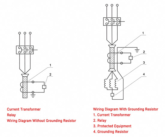
Selection & FAQs
Selection Guide
- Select LJ-2, LJ-4, or LJ-7 from the number of cables, complete bundle size, and 110mm–180mm aperture.
- Confirm the 20/1A or 40/1A ratio, 1A–3A sensitivity, relay pickup, and protection coordination.
- Include every phase and parallel conductor path of the protected circuit through the same core.
- Check relay input, secondary cable length, and total loop resistance against the 10Ω reference.
- Verify bracket mounting, conductor routing, polarity, one-point grounding, secondary shorting, and indoor conditions.
Frequently Asked Questions
Q1: What equipment can the LJ-2/LJ-4/LJ-7 protect?
The series detects earth faults on generators, motors, synchronous condensers, and medium-voltage cable feeders.
Q2: How do LJ-2, LJ-4, and LJ-7 differ?
They support approximately 1–2, 3–4, or 5–7 cable groups and provide 110mm, 140mm, or 180mm windows.
Q3: What current ratios are used?
LJ-2 and LJ-4 use 20/1A, while LJ-7 uses 40/1A.
Q4: What earth-fault sensitivity is specified?
The published reference sensitivity is 1A–3A with a 0.03A relay setting.
Q5: Which relay is typically connected?
The series is commonly paired with a DD-11/60 or an equivalent residual-current relay.
Q6: Must parallel conductors pass through the same core?
Yes. All parallel paths for every protected phase must pass through together to avoid false residual-current measurement.
Q7: Why is secondary loop resistance important?
Excessive relay and cable resistance reduces secondary current and can prevent the protection from reaching its specified sensitivity.