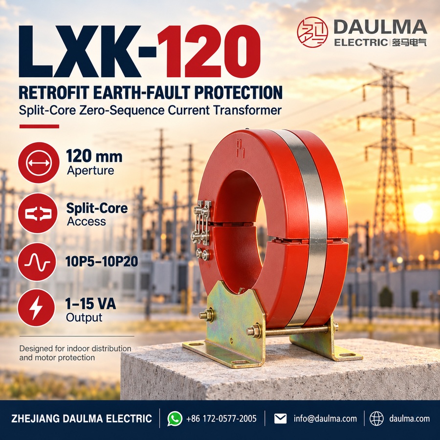
Overview
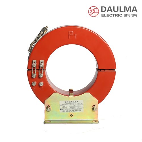
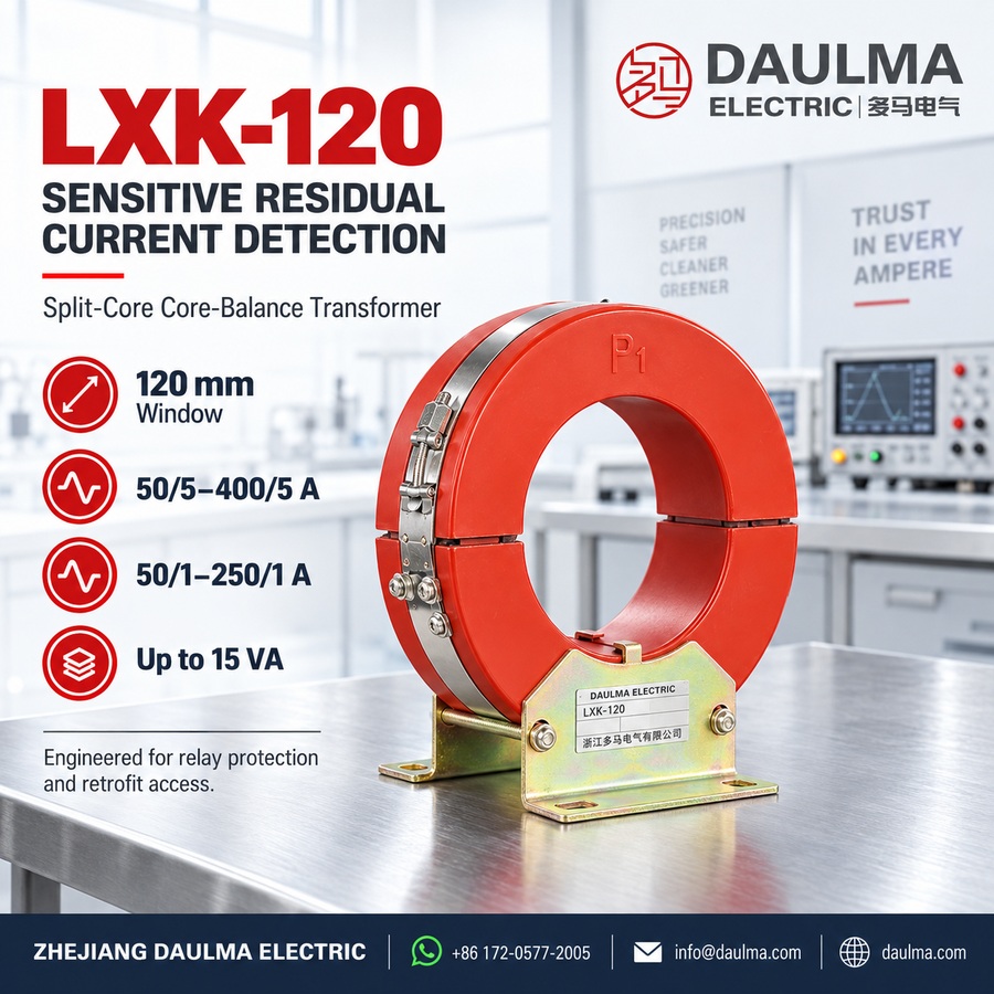
The LXK-120 split-core zero-sequence current transformer is a protective core-balance CT engineered for reliable earth-fault detection in low and medium-voltage AC power systems up to 10 kV. Operating on electromagnetic induction principles, it measures the vector sum of phase currents passing through its aperture to detect residual (zero-sequence) current during ground fault events, delivering a precise signal for relay tripping or alarm activation.
Its split-core clamshell design enables retrofit installation around live cables without system interruption, making it ideal for indoor switchgear, motor protection, generator stator monitoring, and distribution networks requiring dependable ground-fault coverage.
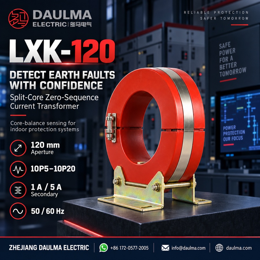
Key Ratings Snapshot
| Parameter | Value |
|---|---|
| System voltage class | <=10 kV |
| Rated frequency | 50 Hz / 60 Hz |
| Rated secondary current | 1 A or 5 A |
| Accuracy classes | 10P5 to 10P20 |
| Rated burden | 1:15 VA |
| Insulation level | 0.72/3 kV |
| Cable aperture diameter | phi120 mm |
| Ambient temperature | -25 deg C to +40 deg C |
| Structure type | Split-core with stainless steel band |
| Installation method | Retrofit, no cable disconnection |
Model Designation
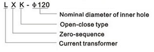
- L: Current transformer (CT)
- X: Zero-sequence (residual current detection)
- K: Split-core (clamshell opening) structure
- 120: Nominal aperture diameter (mm)
Construction
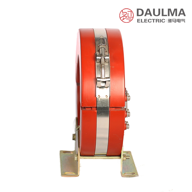
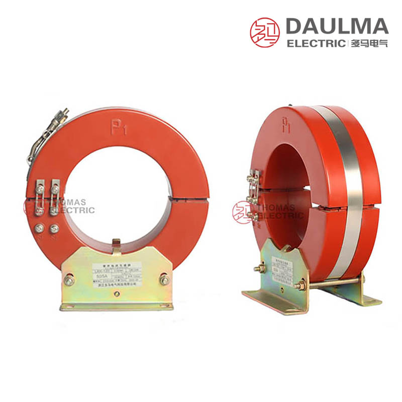
The LXK-120 features an indoor epoxy resin cast construction with a split-core (clamshell) mechanical design, allowing installation around existing cables without primary circuit disconnection. Two semi-circular resin sections are secured by a corrosion-resistant stainless steel fastening band, ensuring stable insulation performance, moisture resistance, and long-term mechanical integrity in confined switchgear environments.
The toroidal magnetic core is optimized for high sensitivity to residual currents, while the fully enclosed resin housing provides robust protection against contamination, humidity, and electrical aging. With no primary terminalsâonly cable conductors passing through the apertureâthe design simplifies field deployment and enhances safety during retrofit projects.
Technical Parameters
Service Conditions
- Installation environment: Indoor only
- Altitude: <= 1000 m
- Ambient temperature: -25 deg C to +40 deg C
- Relative humidity: Daily average <= 95%, monthly average <= 90%
- Environmental conditions: Free from corrosive gases, explosive media, severe vibration or impact
- Outdoor application: Not suitable; requires factory consultation if needed
Technical Data
| Model Configuration |
Accuracy Class |
Rated Current Ratio (A) |
Rated Output (VA) |
|---|---|---|---|
| LXK-120 (120/204×57) | 10P5 to 10P15 | 50/5 to 400/5 50/1 to 250/1 |
1:10 |
| LXK-120 (120/210×65) | 10P5 to 10P15 | 50/5 to 400/5 50/1 to 250/1 |
2.5:10 |
| LXK-120 (120/210×100) | 10P5 to 10P20 | 50/5 to 400/5 50/1 to 250/1 |
2.5:15 |
| LXK-120 (120/250×80) | 10P5 to 10P20 | 50/5 to 400/5 50/1 to 250/1 |
1:15 |
Installation & Wiring
Installation Diagram
Open the split-core by releasing the stainless steel fastening band, position the transformer around all three-phase conductors (ensuring no gaps), and securely close the core halves. Connect secondary terminals K1/K2 to the protection relay using appropriate wiring to minimize burden. Maintain clearance for heat dissipation and future access.
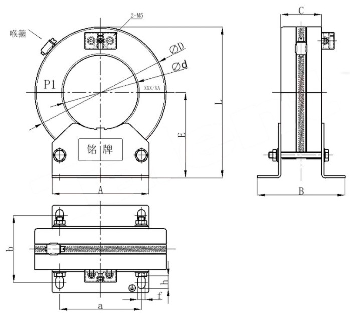
Outline Dimensions
| Model | phid | phiD | C | a | b | A | B | E | L | f | h |
|---|---|---|---|---|---|---|---|---|---|---|---|
| LXK-120 | 120 | 204 | 57 | 110 | 90 | 130 | 120 | 121 | 223 | 10 | 17 |
Installation Critical Notes:
- All phase conductors must pass through the aperture together for correct residual current measurement.
- Ensure core mating surfaces are clean and fully closed; any gap or foreign matter reduces accuracy and sensitivity.
- Tighten the band clamp evenly to maintain stable magnetic coupling and mechanical integrity.
- Follow the protection scheme for cable screen/armor/PE conductor routing (do not mix unintentionally).
Selection & FAQs
Selection Guide
- Confirm the grounding method, minimum detectable earth-fault current, relay pickup setting and required accuracy-limit class.
- Verify the complete cable bundle fits the 120mm aperture, then compare the 57mm, 65mm, 80mm and 100mm structures against cabinet space.
- Choose a 1A or 5A secondary and an available ratio from 50A to 400A that coordinates with the protection relay.
- Calculate relay and secondary-lead burden, then select a configuration whose 1–15VA rated output and 10P5–10P20 class cover the duty.
- Plan all phase and screen/armour/PE routing, K1/K2 polarity, mounting access and safe de-energized installation before ordering.
Frequently Asked Questions
Q1: How does the LXK-120 detect an earth fault?
All phase conductors pass through the same magnetic core. Their balanced currents cancel, while an earth-fault residual produces a secondary signal for the connected relay.
Q2: Can it be installed without disconnecting primary cables?
Yes. Releasing the stainless-steel band opens the two core halves so they can be placed around an existing bundle. Installation must still follow the site’s isolation and electrical-safety procedure.
Q3: Which ratios and secondary currents are available?
Catalogue options include 50/5A–400/5A and 50/1A–250/1A. Select the ratio and 1A or 5A secondary to suit relay input and expected fault current.
Q4: How do the four LXK-120 structures differ?
They share a 120mm aperture but have different outer diameters and widths. The larger-core versions support up to 10P20 and 15VA, while compact versions provide lower maximum burden.
Q5: Can this CT be used in a 10kV cable system?
Yes, when the primary cables provide the system-voltage insulation and the complete installation meets 10kV clearance requirements. The CT’s own published insulation level is 0.72/3kV.
Q6: How should the cable screen and armour be routed?
Routing depends on the grounding scheme and whether screen current must be included in the residual sum. Follow the protection drawing; unintended passage through or around the core can cause missed or false operation.
Q7: What causes loss of sensitivity after installation?
Gaps, dirt or damage at the split faces, uneven band tightening, incorrect conductor routing, reversed K1/K2 polarity and excessive secondary burden can impair protection performance.