Overview
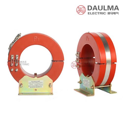
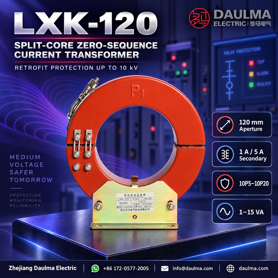
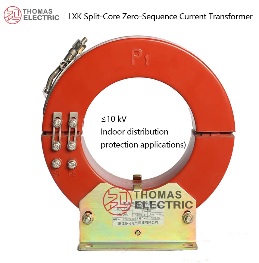
The LXK-120 is a split-core zero-sequence current transformer designed for earth-fault detection in AC power systems up to 10 kV. It features an indoor epoxy resin cast-insulation construction, providing reliable dielectric strength and environmental resistance for long-term operation in switchgear and distribution environments.
Rated with protection accuracy classes from 10P5 to 10P20, it delivers precise residual current measurement for ground-fault protection in generators, motors, and medium-voltage distribution networks. The device complies with GB/T 20840.1-2010 and GB/T 20840.2-2014, aligning with the IEC 61869 framework for instrument transformers.
Key Ratings Snapshot
| Parameter | Rating |
|---|---|
| System voltage class | ≤10 kV |
| Rated frequency | 50 Hz / 60 Hz |
| Rated secondary current | 1 A or 5 A |
| Accuracy class | 10P5 to 10P20 |
| Rated burden | 1–15 VA |
| Insulation level | 0.72/3 kV |
| Ambient temperature | −25 °C to +40 °C |
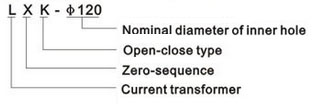
Model Designation
- L: Current transformer (CT)
- X: Zero-sequence (residual current detection)
- K: Split-core (clamshell opening) structure
- 120: Nominal aperture diameter (mm)
Construction
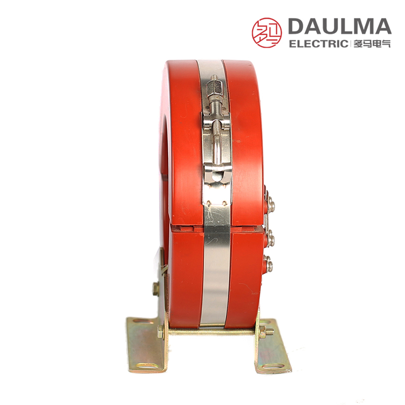
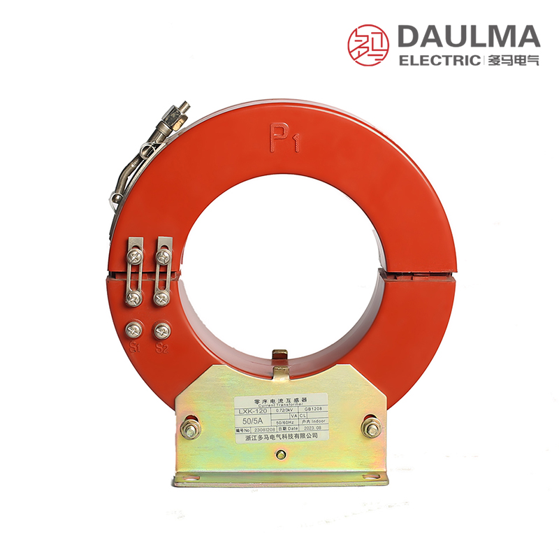
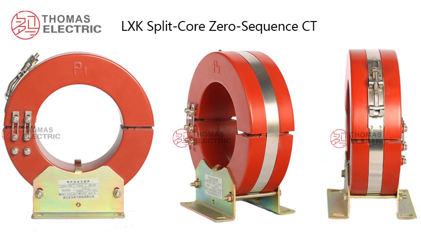
The LXK-120 employs a split-core (clamshell) cable-type design with fully enclosed epoxy resin cast insulation, ensuring stable dielectric performance, moisture resistance, and mechanical robustness for indoor use. The toroidal magnetic core is optimized for zero-sequence current detection, while a stainless steel fastening band secures the two semi-circular halves around existing cables—enabling retrofit installation without primary circuit interruption. Secondary terminals are marked K1 and K2, following standard zero-sequence CT polarity conventions; one point of the secondary circuit must be grounded per applicable standards. Metallic components include anti-corrosion treatment for long-term reliability in typical switchgear environments.
Technical Parameters
Service Conditions
- Installation environment: Indoor installation only
- Altitude: ≤ 1000 m (higher altitude requires engineering confirmation)
- Ambient temperature: −25 °C to +40 °C
- Relative humidity: Daily average ≤ 95%, monthly average ≤ 90%
- Environmental conditions: Free from corrosive gases/vapors, explosive or flammable media; no severe vibration, mechanical shock, or impact
- Outdoor application: Not suitable for outdoor service; if required, use an appropriate enclosure and consult factory
Technical Parameters
The LXK-120 split-core zero-sequence current transformer is designed for ≤10 kV systems with cast-resin insulation, operating within −25 °C to +40 °C ambient temperature and up to 1000 m altitude. It complies with IEC 61869 / GB 20840 standards and supports primary current ratios from 50/1 A to 400/5 A.
Model Variants
| Model Configuration |
Accuracy Class (Protection/ Measurement) |
Rated Current Ratio (A) |
Rated Output (VA) |
|---|---|---|---|
| LXK-120 (120/204×57) | 10P5 to 10P15 | 50/5 to 400/5 50/1 to 250/1 |
1–10 |
| LXK-120 (120/210×65) | 10P5 to 10P15 | 50/5 to 400/5 50/1 to 250/1 |
2.5–10 |
| LXK-120 (120/210×100) | 10P5 to 10P20 | 50/5 to 400/5 50/1 to 250/1 |
2.5–15 |
| LXK-120 (120/250×80) | 10P5 to 10P20 | 50/5 to 400/5 50/1 to 250/1 |
1–15 |
General Technical Parameters
| Parameter | Specification |
|---|---|
| Rated Insulation Level (kV) |
0.72/3 kV (rated insulation voltage / power-frequency withstand voltage) |
| Rated Frequency (Hz) |
50 Hz / 60 Hz |
| Rated Secondary Current (A) |
5 A or 1 A |
| Secondary winding power-frequency withstand voltage | 3 kV |
| Ambient Temperature Range (°C) |
−25 °C to +40 °C |
| Aperture Diameter (mm) |
120 mm (verify cable OD and installation clearance) |
| Applicable system neutral grounding | Grounded or ungrounded neutral systems (specify during ordering) |
Installation & Wiring
Installation Diagram
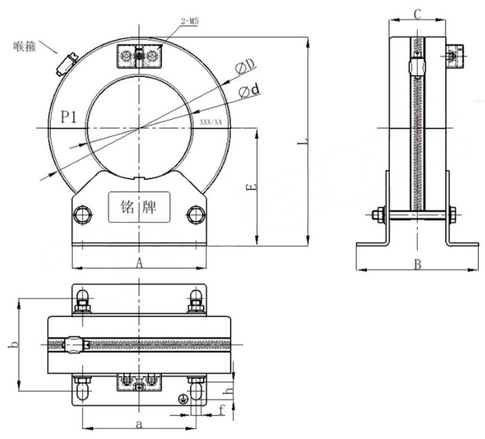
The LXK-120 split-core zero-sequence current transformer is installed by opening the core halves via the stainless steel fastening band, encircling all phase conductors together through the aperture, and securely closing the core to ensure full mating of the surfaces. Proper alignment and clamping are essential for accurate ground fault detection.
Installation Critical Notes:
- All phase conductors must pass through the aperture together for correct residual current measurement.
- Ensure core mating surfaces are clean and fully closed; any gap or foreign matter reduces accuracy and sensitivity.
- Tighten the band clamp evenly to maintain stable magnetic coupling and mechanical integrity.
- Follow the protection scheme for cable screen/armor/PE conductor routing (do not mix unintentionally).
Selection & FAQs
Selection Guide
- Confirm the system grounding method, prospective earth-fault current, relay pickup setting and required 10P accuracy class.
- Check that the complete three-phase cable bundle fits the 120mm aperture, then select the 57mm, 65mm, 80mm or 100mm core-width version to suit the available panel space.
- Choose a 1A or 5A secondary and a ratio within 50/1A–250/1A or 50/5A–400/5A that matches the connected protection relay.
- Add the relay input burden and secondary lead burden, then verify the selected model can supply the required output within its 1–15VA range.
- Plan for all phase conductors to pass through the core in the same direction; confirm screen, armour and PE routing, terminal polarity and access for fully cleaning and closing the split faces.
Frequently Asked Questions
Q1: What is the LXK-120 used for?
It detects residual current for earth-fault protection in indoor cable circuits up to 10kV. It is a protection CT rather than a revenue-metering CT.
Q2: Which transformation ratios are available?
Available ranges are 50/1A to 250/1A with a 1A secondary and 50/5A to 400/5A with a 5A secondary. The final ratio should match the relay setting and expected fault-current range.
Q3: How do the four LXK-120 versions differ?
They share a 120mm aperture but use different core widths and overall dimensions. Depending on the version, rated output is 1–15VA and protection class is available from 10P5 to 10P20.
Q4: Can it be installed without disconnecting the cable?
Yes. The stainless-steel band releases the split core so it can be fitted around an existing cable bundle, making it suitable for retrofit protection projects.
Q5: Why can it be used on systems up to 10kV when its insulation rating is 0.72/3kV?
The primary conductor retains the system-voltage insulation; the CT measures residual current around the insulated cable bundle. Installation clearances and the complete system insulation design must still meet the applicable 10kV requirements.
Q6: Which conductors should pass through the aperture?
All phase conductors of the protected circuit must pass through the core together and in the same direction. Screen, armour and protective-earth conductors must be routed according to the grounding scheme to avoid cancelling or creating residual current.
Q7: What installation issues most often reduce sensitivity?
Dirty or damaged split faces, an incompletely closed core, uneven band tightening, incorrect cable or screen routing, reversed K1/K2 connections and excessive secondary burden can all impair protection performance.