Overview
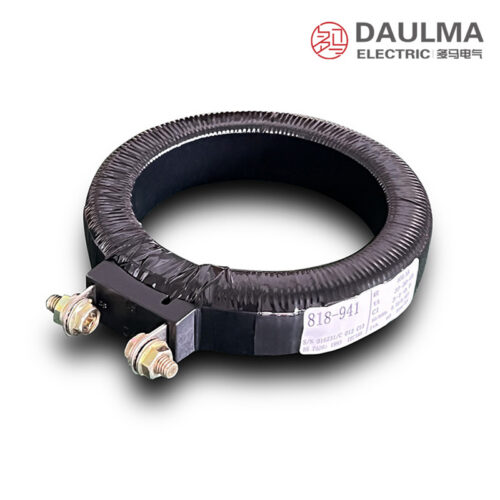
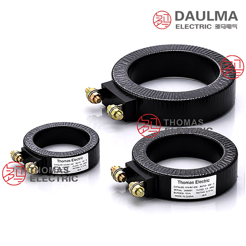
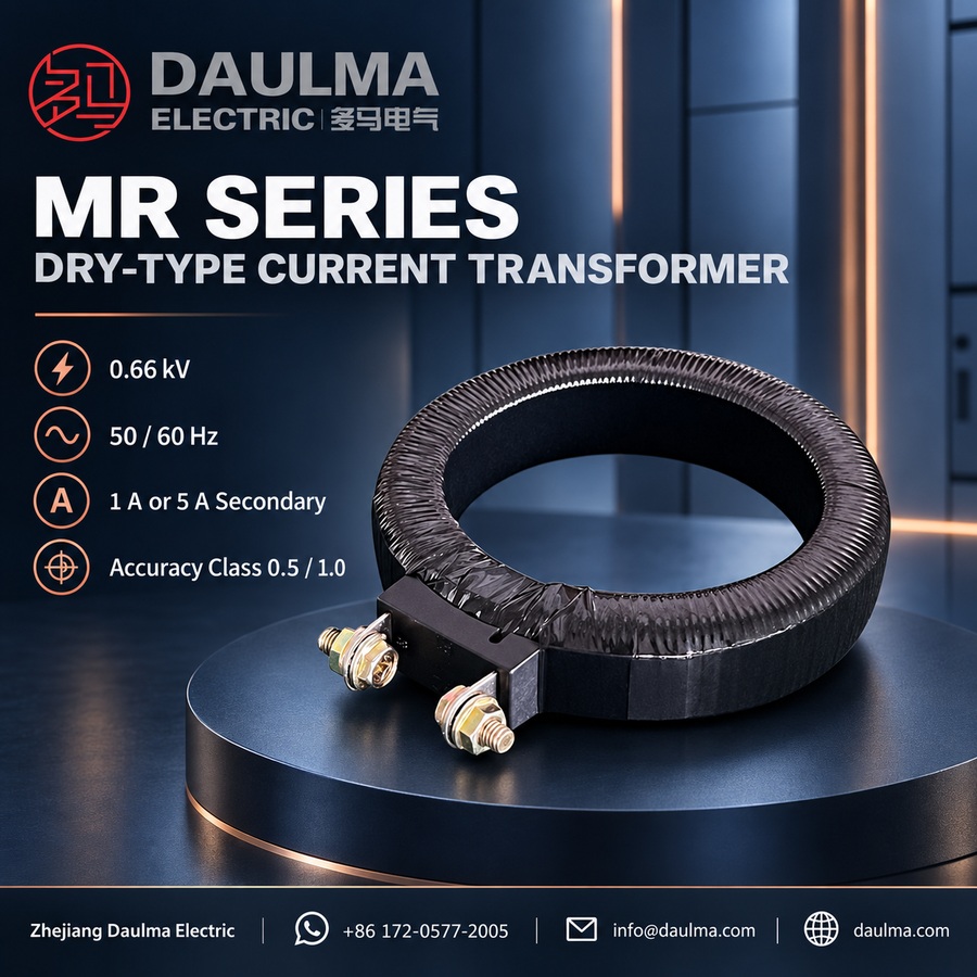
The MR series dry-type current transformers are precision electromagnetic instruments designed for accurate current measurement, energy metering, and relay protection in low-voltage AC power systems. Operating at 50 Hz or 60 Hz, they use electromagnetic induction to deliver galvanically isolated secondary current signals proportional to the primary current.
Built for 0.66 kV applications, these transformers feature a window-type design that simplifies installation by allowing the primary conductor to pass directly through the core apertureâeliminating complex wiring while ensuring reliable electrical isolation and long-term performance in indoor environments.
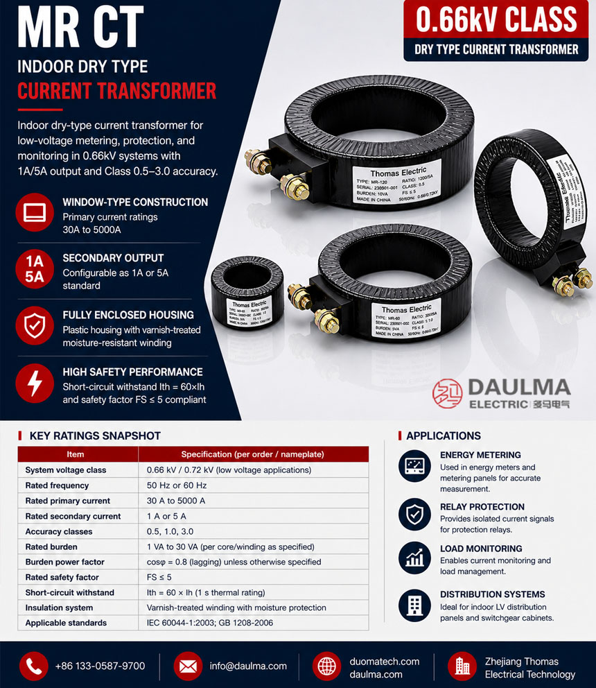
Key Ratings Snapshot
| Item | Specification |
|---|---|
| System voltage class | 0.66 kV / 0.72 kV |
| Rated frequency | 50 Hz or 60 Hz |
| Rated primary current | 30 A to 5000 A |
| Rated secondary current | 1 A or 5 A |
| Accuracy classes | 0.5, 1.0, 3.0 |
| Rated burden | 1 VA to 30 VA |
| Burden power factor | cos phi = 0.8 (lagging) |
| Rated safety factor | FS <= 5 |
| Short-circuit withstand | Ith = 60 x Ih (1 s) |
| Insulation system | Varnish-treated winding with moisture protection |
Construction
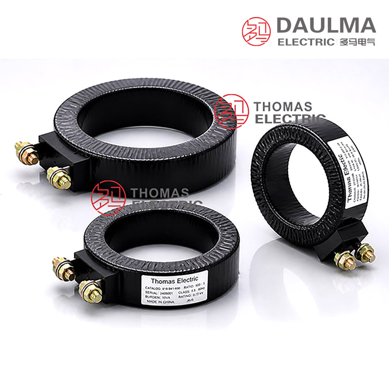
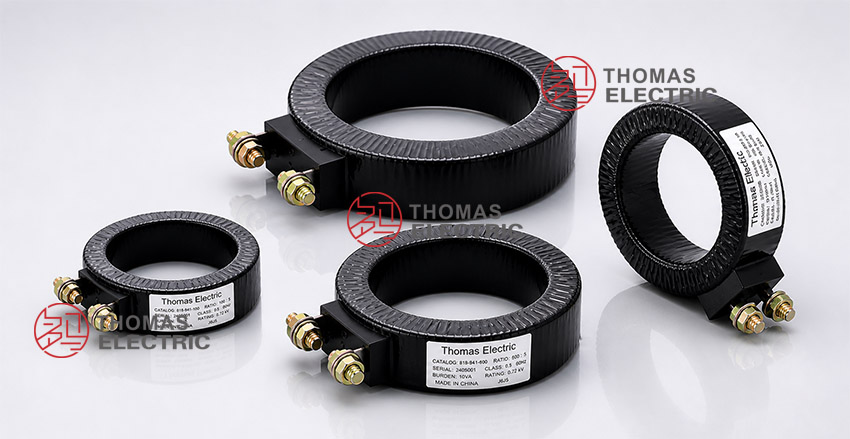
The MR transformer features a fully enclosed plastic housing with a toroidal magnetic core and varnish-treated secondary windings, providing superior moisture resistance and mechanical protection for indoor use. The window-type (pass-through) configuration allows the primary conductor to be inserted directly through the aperture, eliminating the need for primary terminals while maintaining excellent electrical isolation.
Secondary terminals are clearly marked as K/L or S1/S2 following standard CT polarity conventions. This design ensures reliable performance in metering, protection, and monitoring applications within low-voltage distribution systems up to 0.66 kV.
Technical Parameters
Service Conditions
- Installation environment: Indoor installation only
- Altitude: Not exceeding 1000 m above sea level
- Ambient temperature: -5 deg C to +40 deg C
- Relative humidity: Daily average <= 95%, monthly average <= 90% (at +20 deg C reference)
- Environmental conditions: Free from corrosive gases, explosive media, severe vibration, or mechanical shock
Technical Data
| Type | Ratio (A) | Burden (VA) | |
|---|---|---|---|
| Class 0.5 | Class 1.0 | ||
| MR-28 | 50/5, 60/5, 75/5 | – | 1.5 |
| 100/5 | 1.5 | 2.5 | |
| MRT-40 | 100/5, 150/5 | 1.5 | 2.5 |
| 200/5 | 2.5 | 5 | |
| 250/5, 300/5 | 3.75 | 5 | |
| MR-42 | 100/5, 150/5 | 1.5 | 2.5 |
| 200/5 | 2.5 | 5 | |
| 250/5, 300/5 | 3.75 | 5 | |
| MR-45 | 250/5 | 3.75 | 5 |
| 300/5, 400/5 | 5 | 7.5 | |
| MR-60 | 300/5 | 3.75 | 5 |
| 400/5 | 5 | 7.5 | |
| 500/5 | 5 | 10 | |
| 600/5, 800/5 | 7.5 | 10 | |
| MRT-70 | 600/5 | 5 | 10 |
| 800/5 | 7.5 | 10 | |
| 1000/5, 1200/5, 1500/5, 1600/5 | 10 | 15 | |
| MR-85 | 600/5 | 5 | 10 |
| 800/5 | 7.5 | 10 | |
| 1000/5, 1200/5, 1500/5, 1600/5 | 10 | 15 | |
| MR-125 | 2000/5, 2500/5, 3000/5 | 15 | 20 |
| 4000/5, 5000/5 | 20 | 30 | |
Installation & Wiring
Installation Diagram
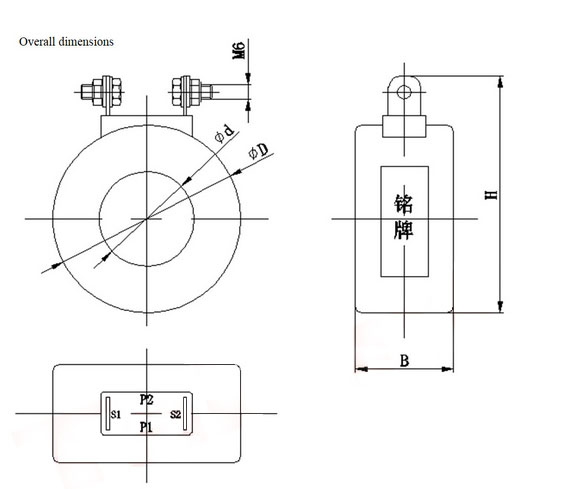
The primary conductor passes through the transformer window aperture; ensure conductor size fits within the specified opening. Mount the unit securely using the provided holes or brackets, maintain adequate clearance for heat dissipation, and observe terminal polarity (K/L or S1/S2) to ensure correct secondary current direction.
Outline Dimensions
| 型号 | φD | φd | B | H |
|---|---|---|---|---|
| MR-28 | 76 | 28 | 37 | 98 |
| MRT-40 | 80 | 41 | 41 | 102.5 |
| MR-42 | 76 | 42 | 36 | 105.5 |
| MR-45 | 77 | 45 | 36 | 106 |
| MR-60 | 93 | 60 | 27 | 116 |
| MRT-70 | 119 | 70 | 42 | 142 |
| MR-85 | 124 | 85 | 28 | 146 |
| MR-125 | 157 | 125 | 28 | 188 |
Selection & FAQs
Selection Guide
- Select the 50/5A–5000/5A ratio from maximum operating current and required measurement range.
- Choose MR-28 through MR-125 by conductor dimensions, window clearance, and panel space.
- Specify class 0.5 or 1.0 and confirm the available VA output for the selected ratio.
- Calculate total burden and verify the 60 × rated-current, 1-second thermal withstand against fault duty.
- Confirm mounting, conductor direction, polarity, grounding, terminal access, and indoor conditions.
Frequently Asked Questions
Q1: Is outdoor installation permitted for this 0.66kV low voltage current transformer?
No, it is strictly for indoor installation only. The service conditions require an environment free from corrosive gases and severe vibration. Contact our engineering team for outdoor-rated alternatives.
Q2: Which accuracy class should I select for standard metering?
Choose Class 0.5 or Class 1.0 depending on your burden requirements. For example, MR-42 at 100/5A supports 1.5VA for Class 0.5 and 2.5VA for Class 1.0. Specify your exact burden during inquiry.
Q3: What are the maximum altitude and temperature limits for operation?
The maximum operating altitude is 1000 meters above sea level. The ambient temperature must remain between -5°C and +40°C during standard operation. Applications exceeding these environmental limits require special factory evaluation.
Q4: Can I customize the current ratio for this MR series?
Yes, standard ratios range from 50/5A to 400/5A across various frame sizes. Custom ratios are available subject to factory confirmation. Provide your specific primary and secondary current requirements for a quote.
Q5: Are specific factory test reports provided before shipment?
Standard routine tests are conducted to ensure compliance with rated burdens and accuracy classes. Specific type test reports or third-party certifications are subject to confirmation. Contact our sales team for detailed test documentation.
Q6: How is this dry-type current transformer typically applied in low voltage?
It is primarily used for current measurement and relay protection in 0.66kV indoor low voltage distribution systems. The dry-type design ensures safe integration within standard switchgear panels. Request the dimension drawing for panel layout verification.