Overview
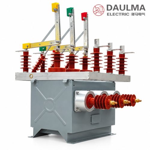
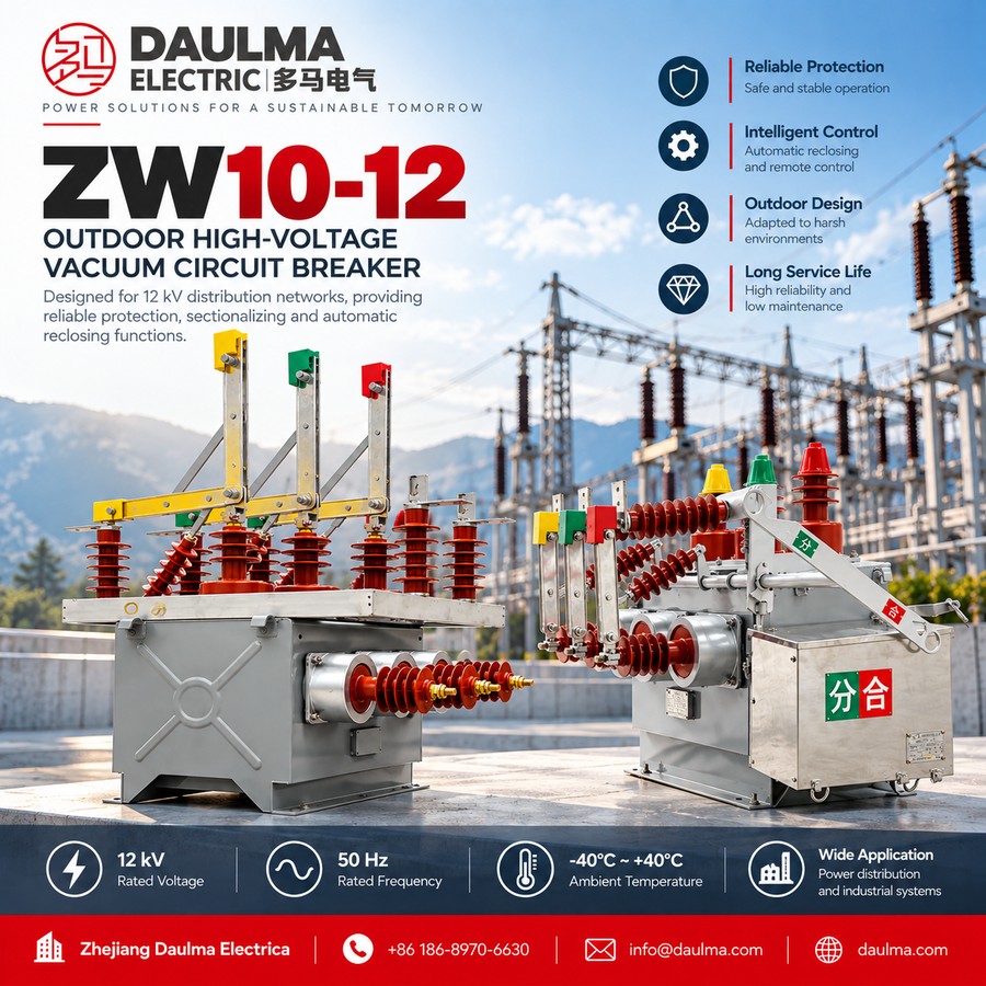
The ZW10-12XDG Series high-voltage dual-power automatic transfer switching device is an outdoor vacuum-circuit-breaker-based unit for AC 50Hz, 12kV distribution systems with two supply sources and rated current up to 630A. It is made up of a high-vacuum circuit breaker and an intelligent controller. When one supply source fails or drops to undervoltage, the device automatically transfers the load to the healthy source to guarantee continuous power supply, and reverts to the normal source once it is restored (self-transfer and self-revert).
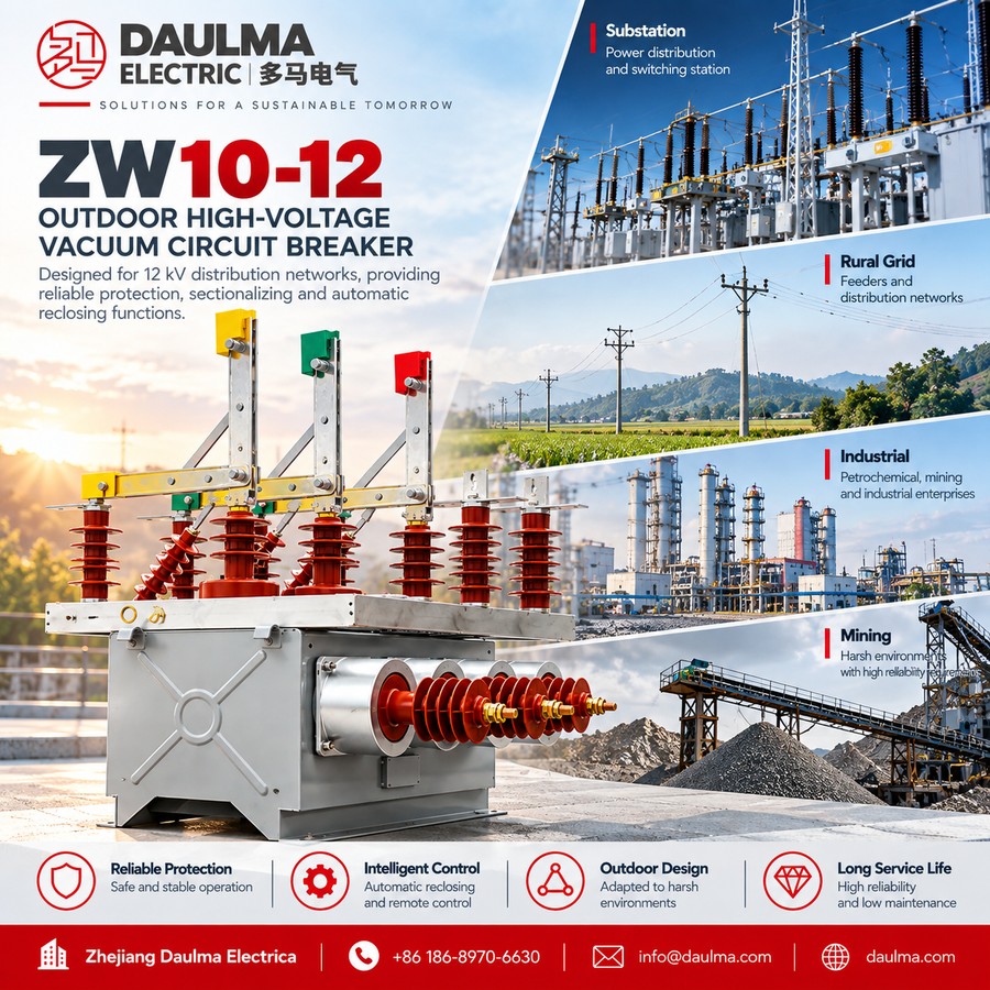
The device provides short-circuit and overcurrent protection with interlock functions, effectively preventing unnecessary re-energization impact during load faults, and ensures complete electrical isolation between the two high-voltage sources. Reliable mechanical and electrical interlocking gives the unit a very high level of safety. It is intended as the control and protection device of dual-power supply systems for users with high requirements on supply reliability, and is widely used on 10kV distribution lines in oil fields, mines, metallurgy, chemical, railway, communication and machinery applications.
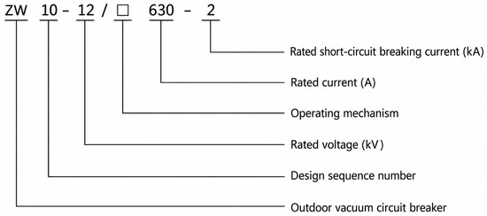
Model Designation
Construction
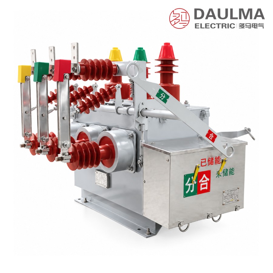
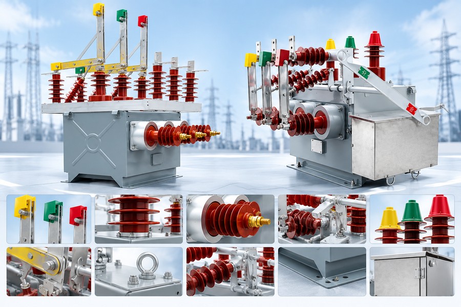
The ZW10-12XDG adopts a three-phase column structure with vacuum interrupters housed in a sealed tank on a common base frame. The incoming and outgoing terminals (A-side and B-side) are arranged for two independent power sources, and an external stainless-steel mechanism box houses the spring-storage mechanism, the intelligent controller and the transfer logic.
The intelligent controller monitors both supply sources and performs automatic transfer and reversion. Short-circuit and overcurrent protection, together with mechanical and electrical interlock, prevent parallel operation of the two sources, and a manual operating handle is provided for emergency operation. The hermetically sealed vacuum interrupters ensure a long maintenance-free service life in harsh outdoor environments.
Technical Parameters
Service Conditions
- Ambient air temperature: -40 degC to +40 degC
- Altitude: <= 1000 meters (higher altitude on request with derating)
- Earthquake intensity: <= Grade 8
- Relative humidity: daily average <= 95%; monthly average <= 90%
- Site requirement: free from fire, explosion, severe pollution, chemical corrosion, or violent vibration
Technical Data
| No. | Item | Unit | Data |
|---|---|---|---|
| 1 | Rated Voltage | kV | 12 |
| 2 | Highest Operating Voltage | kV | 12 |
| 3 | Rated Current | A | 630 |
| 4 | Rated Short-Circuit Breaking Current | kA | 20 |
| 5 | Rated Short-Circuit Making Current (Peak) | kA | 50 |
| 6 | Rated Peak Withstand Current | kA | 50 |
| 7 | Rated Short-Time Withstand Current | kA | 20 |
| 8 | Power Frequency Withstand Voltage (Dry) | kV | 42 |
| Lightning Impulse Withstand Voltage (Peak) | kV | 75 | |
| 9 | Rated Operating Sequence | – | O-0.3s-CO-180s-CO |
| 10 | Mechanical Life | operations | 10000 |
| 11 | Number of Rated Short-Circuit Breaking Operations | times | 30 |
| 12 | Rated Closing Voltage of Operating Mechanism | V | 220 |
| 13 | Rated Opening Voltage of Operating Mechanism | V | 220 |
| 14 | Contact Gap | mm | 9 ± 1 |
| 15 | Over-Travel | mm | 3 ± 0.5 |
| 16 | Three-Phase Opening/Closing Non-Simultaneity | ms | <= 2 |
| 17 | Contact Closing Bounce Time | ms | <= 2 |
| 18 | Average Opening Speed | m/s | 1.0 ± 0.2 |
| 19 | Average Closing Speed | m/s | 0.7 ± 0.15 |
| 20 | Opening Time (max / min operating voltage) | s | 0.015–0.05 / 0.03–0.06 |
| 21 | Closing Time | s | 0.025–0.05 |
| 22 | Main Circuit Resistance per Phase | µΩ | <= 180 |
| 23 | Accumulative Allowable Wear Thickness of Contacts | mm | 3 |
Installation & Wiring
Installation Diagram
The ZW10-12XDG is designed for pole-mounted or gantry installation. The A-side and B-side terminals connect to the two independent power sources, and the outgoing terminal feeds the load.
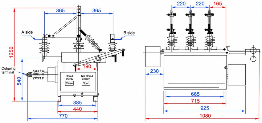
Overall and Mounting Dimensions
| View | Item | Dimension (mm) |
|---|---|---|
| Front view | Overall height | 1250 |
| Lower section height (to outgoing terminal) | 540 | |
| Phase spacing (A-side / center / B-side) | 365 / 365 | |
| Mechanism box width | 190 | |
| Base mounting hole width | 385 / 440 | |
| Overall base width | 770 | |
| Side view | Top bushing spacing | 220 / 220 / 165 |
| Front overhang depth | 230 | |
| Base length | 665 / 715 / 925 | |
| Overall length | 1080 |
Selection & FAQs
Selection Guide
- Confirm a 12kV, 50Hz three-phase dual-power supply system with rated current up to 630A.
- Select rated short-circuit breaking current (20kA) to match the network capacity at the installation point.
- Define the transfer mode: self-transfer / self-revert, preferred source, and transfer delay as required.
- Confirm mechanism control voltage (AC/DC 220V standard; other voltages on request).
- Verify pole/gantry load capacity and overall dimensions (approx. 1250mm height) for the mounting structure.
- For altitudes above 1000m or special service conditions, consult the factory for derating.