Overview
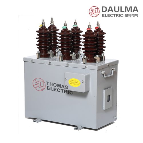
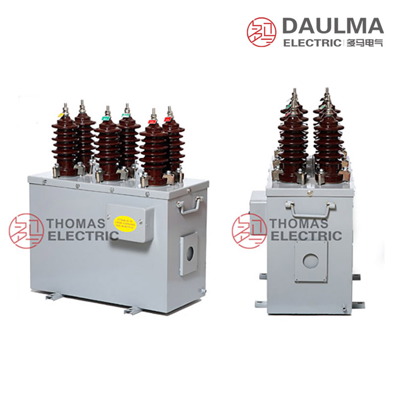
The JLSZW3-6 and JLSZW3-10 series are outdoor dry-type combined instrument transformers integrating voltage transformer (VT) and current transformer (CT) functions in one sealed enclosure. Designed for 6 kV and 10 kV three-phase AC systems at 50 Hz, they deliver galvanically isolated secondary signals for energy metering, protection relaying, and supervisory control in urban/rural grids, outdoor substations, and industrial distribution networks.
These units feature epoxy resin cast insulation, fully enclosed metal housing, and Y/Yo three-phase four-wire connection, ensuring reliable operation under harsh outdoor conditions while maintaining high measurement accuracy and long-term stability.
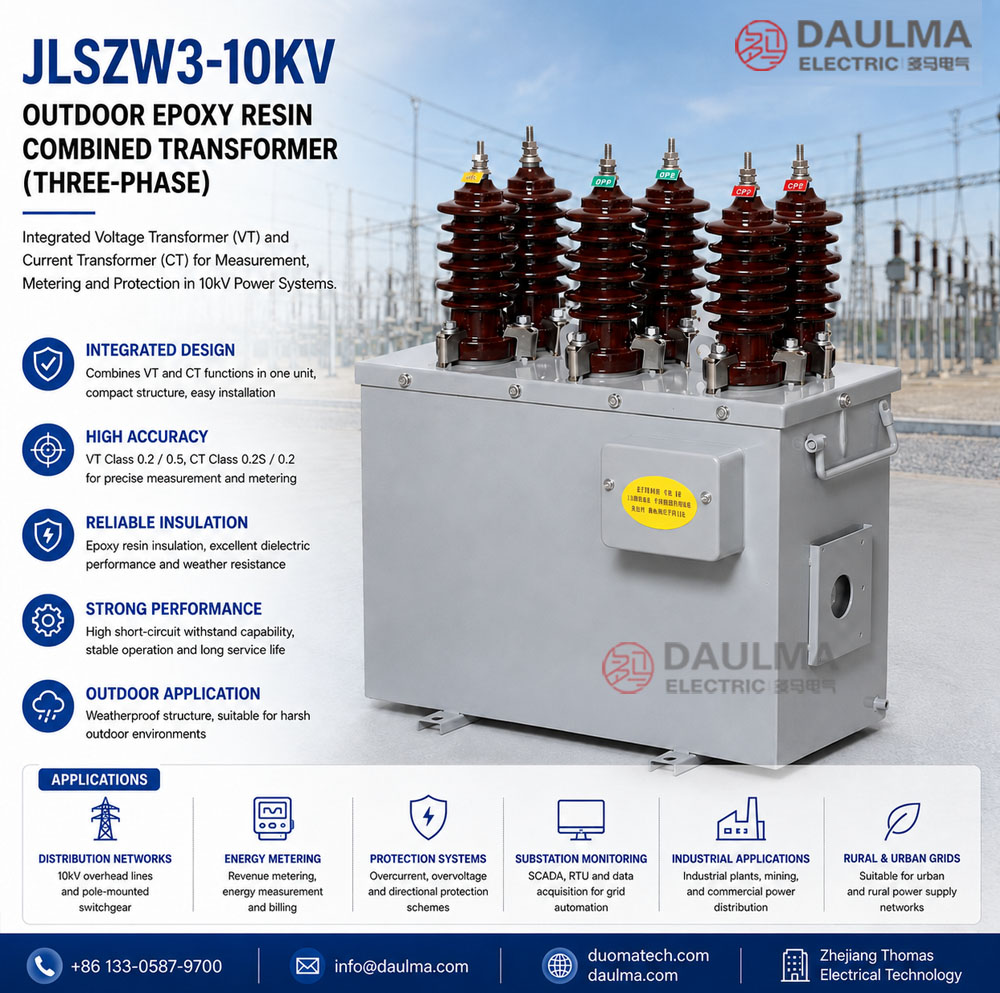
Key Ratings Snapshot
| Parameter | Value |
|---|---|
| System voltage class | 6 kV / 10 kV |
| Rated frequency | 50 Hz (60 Hz on request) |
| VT voltage ratios | 3000/100 V, 6000/100 V, 10000/100 V |
| VT accuracy classes | 0.2 / 0.5 |
| VT rated output | 15 VA / 30 VA per core |
| CT current ratios | 5~200/5 A |
| CT accuracy classes | 0.2S / 0.2 |
| CT rated output | 10 VA per core |
| Connection configuration | Three-phase four-wire Y/Yo |
| Insulation level (JLSZW3-10) | 12/42/75 kV |
Model Designation
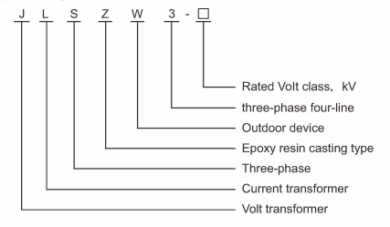
- J: Voltage transformer (VT/PT)
- L: Current transformer (CT)
- S: Three-phase configuration
- Z: Cast-resin (epoxy) insulated structure
- W: Outdoor installation type
- 3: Design series code
- 6 / 10: Voltage class (kV)
Construction
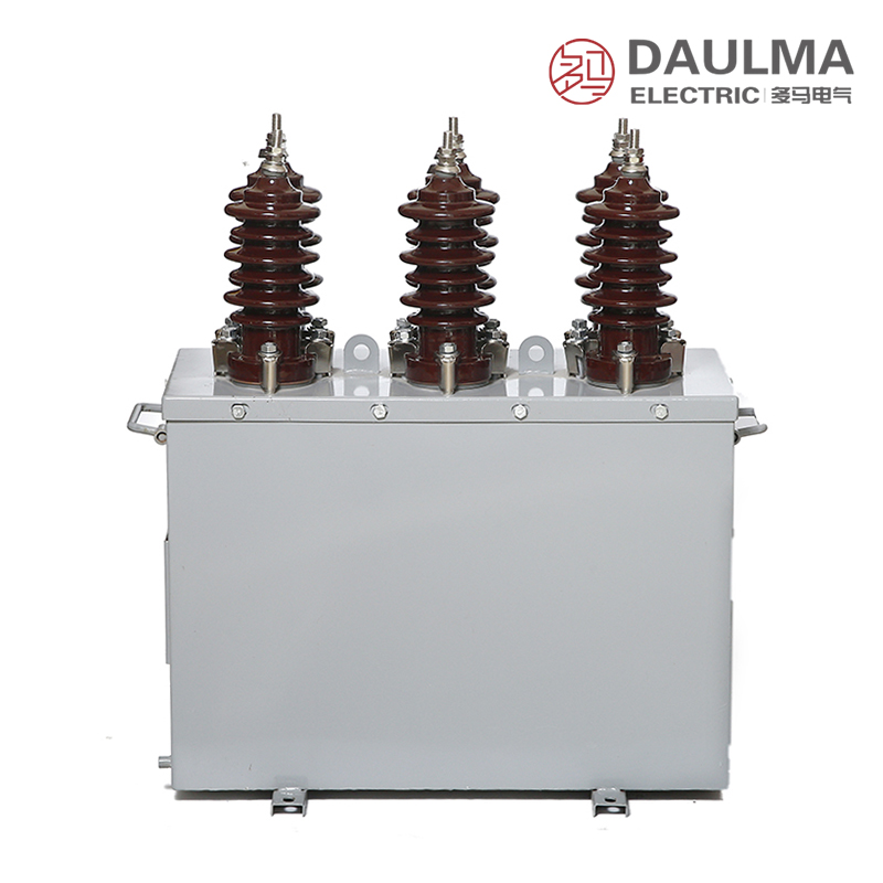
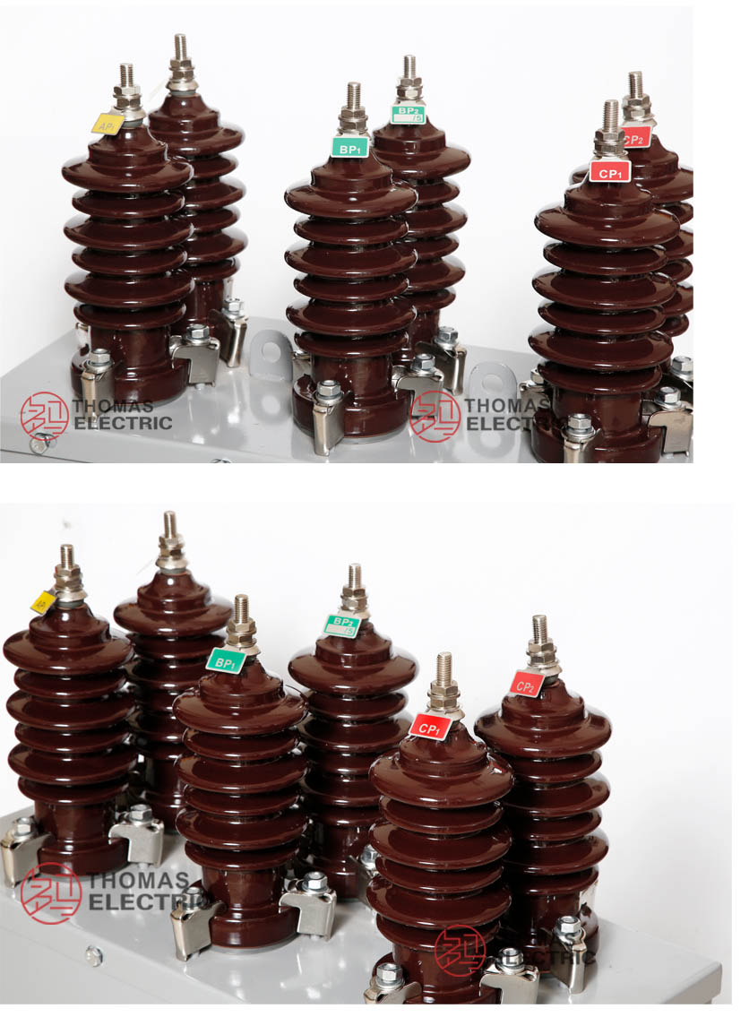
The combined transformer integrates three single-phase VTs and three single-phase CTs within a sealed metal enclosure. The VT sections use wound cores made of cold-rolled grain-oriented silicon steel with epoxy resin cast windings, while the CT sections employ closed toroidal cores with premium silicon steel laminations and monolithic epoxy casting. This design ensures excellent moisture resistance, pollution resistance, and aging stability for reliable outdoor service.
All components are assembled to maintain proper electrical clearances and creepage distances. Primary and secondary terminals are accessible via compartment doors, and the housing provides robust environmental protection against rain, dust, and temperature extremes.
Technical Parameters
Service Conditions
- Installation environment: Outdoor installation in sheltered or exposed locations
- Altitude: Not exceeding 1000 m above sea level
- Ambient temperature: -25 deg C to +40 deg C
- Relative humidity: Daily average <= 95%, monthly average <= 90% (at +20 deg C reference)
- Environmental conditions: Free from severe salt fog, industrial contamination, or explosive atmospheres; no abnormal vibration or mechanical shock
- Lightning protection: Zinc oxide surge arrester required within 1 meter of installation point
Technical Data
| Model | Rated Voltage Ratio (V) |
Accuracy Class |
Rated Output (VA) |
Limit Output (VA) |
Rated Current Ratio (A) |
CT Rated Output (VA) |
Insulation Level (kV) |
|---|---|---|---|---|---|---|---|
| JLSZW3-6 | 3000/100 6000/100 |
0.2 / 0.5 | 15 / 30 | 300 | 5~200/5 | 10 | 7.2/32/60 |
| JLSZW3-10 | 3000/100 6000/100 10000/100 |
0.2 / 0.5 | 15 / 30 | 300 | 5~200/5 | 10 | 12/42/75 |
Installation & Wiring
Installation Diagram
The combined transformer shall be mounted on a stable foundation or pole-mounted bracket with secure mechanical fixing. Primary connections are made via busbar or cable termination, and secondary circuits must be routed through sealed cable glands with strain relief. A zinc oxide surge arrester is mandatory within 1 meter of primary terminals per GB requirements. One point of each secondary circuit (VT neutral and CT secondary) must be reliably grounded.
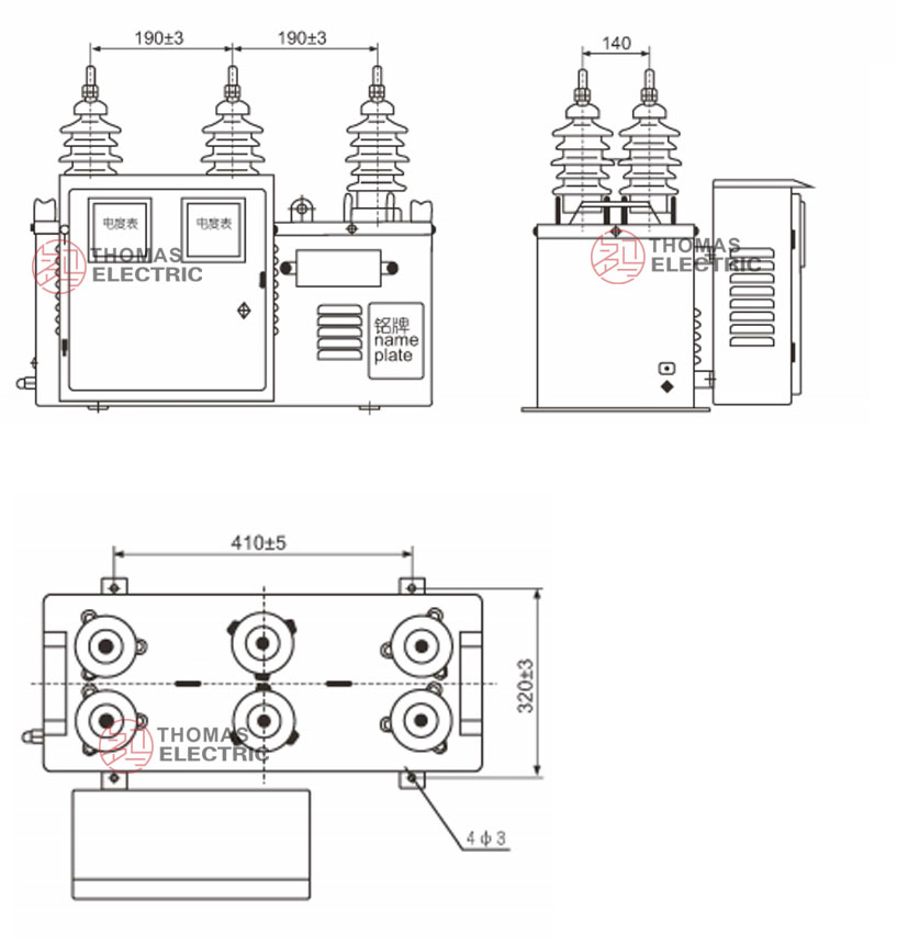
Outline Dimensions
| Dimension | Value (mm) |
|---|---|
| Height | Approx. 850 |
| Width | Approx. 620 |
| Depth | Approx. 380 |
| Mounting base | 4 x phi14 holes, 400 x 300 mm pattern |
| Primary terminal height | Approx. 780 mm above base |
Selection & FAQs
Selection Guide
- Select VT voltage ratio matching system nominal voltage: 10000/100 V for 10 kV systems, 6000/100 V for 6 kV systems
- Choose CT primary current based on continuous load and measurement range; standard ratios from 5/5 A to 200/5 A
- Use VT accuracy class 0.2 and CT class 0.2S for revenue-grade metering; class 0.5 and 0.2 are acceptable for general monitoring
- Select VT rated burden (15 VA or 30 VA) based on total connected load including wiring losses
- Verify CT short-circuit withstand ratings (Ith = 100 x I1n for 1 s, Idyn = 2.5 x Ith peak) against system fault levels
- Confirm outdoor service conditions (temperature, altitude, humidity) match product specifications
Frequently Asked Questions
Q1: Can this epoxy resin transformer be installed in severe salt fog environments?
No, it is not suitable for severe salt fog or industrial contamination. Ensure the installation environment is free from corrosive gases. Contact us for specialized coastal variants if required.
Q2: What is the maximum insulation level for the JLSZW3-10 model?
The JLSZW3-10 features an insulation level of 12/42/75 kV. It supports rated voltage ratios up to 10000/100V. This ensures reliable dielectric performance in standard outdoor switchgear.
Q3: Which accuracy class should be selected for protective relaying applications?
Select the 0.5 accuracy class for general measurement and protection. The 0.2 class is available for precision metering. Specify your exact protection and metering needs for factory configuration.
Q4: How should lightning protection be configured for outdoor installation?
A zinc oxide surge arrester must be installed within 1 meter of the transformer. This prevents overvoltage damage during lightning strikes. Proper grounding of the arrester is also essential.
Q5: Can the current transformer ratio be customized for specific projects?
Yes, custom current ratios from 5/5A to 200/5A are available. Standard voltage ratios include 6000/100V and 10000/100V. Provide your exact ratio requirements for factory quotation.
Q6: Which routine factory tests are performed before shipment?
Standard routine tests include ratio, polarity, and insulation resistance checks. Specific type tests or third-party certifications are subject to project confirmation. Contact our sales team for detailed test reports.
Q7: Where is this dry-type combined transformer typically applied?
It is designed for outdoor power distribution and measurement in 10kV systems. The epoxy resin housing ensures reliable performance in sheltered or exposed locations. Confirm altitude limits with our engineers.