Overview
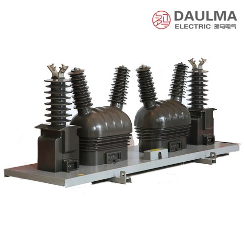
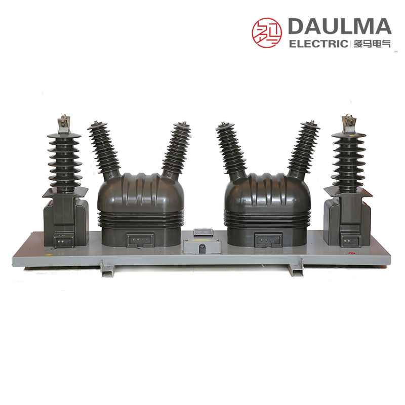
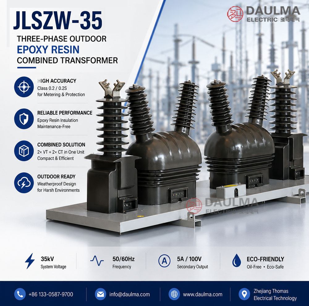
The JLSZW-35 combined instrument transformer integrates voltage and current transformation functions into a single outdoor-rated epoxy resin cast assembly. Designed for 35 kV class AC power distribution systems, it delivers galvanically isolated secondary signals for energy metering, protection relays, and instrumentation. Its compact, oil-free design ensures reliable performance in harsh outdoor environments while eliminating fire risk and environmental contamination.
This three-phase unit employs a V/V-connected VT configuration and CTs on A- and C-phases to enable full three-phase power measurement with reduced component count, lowering installation complexity and cost without compromising accuracy or compliance with international standards.
Key Ratings Snapshot
| Parameter | Value |
|---|---|
| System Voltage Class | 35 kV (Um = 42 kV) |
| Rated Frequency | 50 Hz (60 Hz on request) |
| VT Ratio | 35000:100 V |
| VT Accuracy Classes | 0.2 / 0.5 |
| CT Ratio Range | 5~200:5 A (tap-adjustable) |
| CT Accuracy Classes | 0.2S / 0.2 |
| CT Rated Output | 10 VA per core |
| VT Rated Output | 30 VA (0.2) / 50 VA (0.5) |
| CT Short-Circuit Withstand | Ith = 100xI1n (1 s); Idyn = 2.5xIth |
| Insulation Level | AC 95 kV / LI 195 kV |
Model Designation
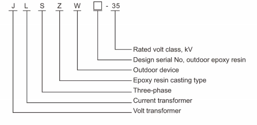
- J: Instrument transformer (general designation)
- L: Current transformer function included
- S: Three-phase configuration (san xiang)
- Z: Pillar/post type mounting structure
- W: Outdoor service (wai hu)
- 35: Voltage class (kV)
Construction
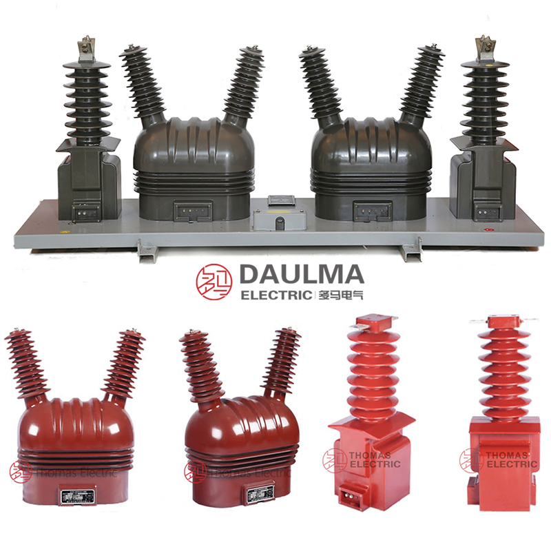
The JLSZW-35 features a fully enclosed, vacuum-cast epoxy resin housing rated for outdoor use with IP54 protection. This construction provides excellent resistance to UV radiation, moisture, pollution, and thermal cycling, ensuring long-term insulation integrity without oil maintenance. The post-type structure allows for pole or platform mounting in outdoor substations while maintaining required electrical clearances and mechanical robustness.
Internal components include two single-phase VTs with silicon steel cores in V/V connection and two window-type CTs with toroidal magnetic cores on A- and C-phases. All windings and terminals are sealed within the weatherproof resin body, with outdoor-rated terminal blocks featuring tracking-resistant barriers and sealing glands for reliable secondary connections.
Technical Parameters
Service Conditions
- Installation environment: Outdoor (protected from severe direct precipitation)
- Altitude: <= 2000 m (higher altitude requires engineering review)
- Ambient temperature: -40 degC to +40 degC
- Relative humidity: Daily average <= 95%, monthly average <= 90%
- Pollution level: Per IEC 60815 (severity to be specified)
- UV exposure: Resin includes UV stabilizers for long-term outdoor service
Technical Data
| Section | Rated Voltage/Current Ratio |
Accuracy Class |
Rated Output (VA) |
Thermal/Dynamic Stability |
Insulation Level (kV) |
|---|---|---|---|---|---|
| VT | 35000:100 | 0.2 | 30 | – | 42/95/195 |
| VT | 35000:100 | 0.5 | 50 | – | 42/95/195 |
| CT | 5~200:5 | 0.2S | 10 | Ith = 100xI1n (1 s) Idyn = 2.5xIth |
42/95/195 |
| CT | 5~200:5 | 0.2 | 10 | Ith = 100xI1n (1 s) Idyn = 2.5xIth |
42/95/195 |
Installation & Wiring
Installation Diagram
The JLSZW-35 must be securely mounted on an outdoor platform or pole using the provided base or bracket. Primary busbar connections are made to designated VT and CT terminals with correct torque. Maintain adequate clearance for insulation coordination, heat dissipation, and maintenance access per local outdoor substation standards. Ground the metallic mounting base and secondary neutral points as required by electrical safety codes.
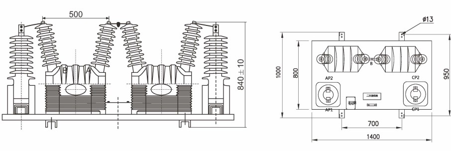
Outline Dimensions
| Dimension | Value (mm) |
|---|---|
| Total Height | 1250 |
| Base Width | 320 |
| Mounting Hole Spacing | 260 |
| Primary Terminal Height | 1100 |
| Secondary Compartment Size | 200 x 150 x 100 |
Selection & FAQs
Selection Guide
- Select VT accuracy class 0.2 for revenue-grade metering; 0.5 for indication or monitoring.
- Choose CT accuracy class 0.2S if high accuracy at light loads (1%~20% of rated current) is required.
- Calculate VT burden as sum of all connected meters, relays, transducers, and wiring losses.
- Determine CT primary rating based on feeder load and verify short-circuit withstand against system fault levels.
- Confirm outdoor pollution severity and altitude during ordering for proper insulation coordination.
- Specify grounding scheme, terminal arrangement, and documentation language per local utility requirements.
Frequently Asked Questions
Q1: Is this 35kV combined transformer suitable for outdoor UV exposure?
Yes, it is designed for outdoor installation. The epoxy resin includes UV stabilizers for long-term service. Confirm specific pollution levels per IEC 60815 with our engineering team.
Q2: What are the thermal and dynamic stability ratings for the CT?
The current transformer offers high short-circuit withstand capability. Thermal stability is 100x In for 1 second, and dynamic stability is 2.5x Ith. These ratings ensure reliable operation during fault conditions.
Q3: Which accuracy class should I select for revenue metering applications?
Select the 0.2S accuracy class for the current transformer. It guarantees precise measurements for billing purposes across the 5 to 200A primary current range. Factory calibration certificates are provided upon request.
Q4: Can the primary current ratio be customized for our specific substation?
Yes, the CT primary current ratio can be tailored. Standard options range from 5A to 200A, but custom ratios are available subject to factory engineering review. Please provide your exact requirements for a formal quotation.
Q5: Are standard factory tests provided before shipping the 35kV transformer?
Standard routine tests verify ratio, polarity, and insulation integrity. The unit withstands standard impulse and power-frequency voltage levels up to 195kV. Request the specific test certificate format prior to ordering.
Q6: How does the JLSZW-35KV handle high-altitude installation requirements?
The unit is rated for altitudes up to 2000 meters. For installations above this elevation, derating factors apply and require special engineering review. Specify your exact site altitude during the initial inquiry.
Q7: Why choose epoxy resin for this 35kV combined instrument transformer?
Epoxy resin provides excellent environmental sealing and mechanical strength. It operates reliably in ambient temperatures from -40°C to +40°C with daily humidity up to 95%. Confirm local microclimate conditions with our technical team.