Overview
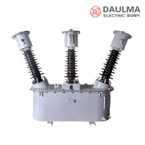
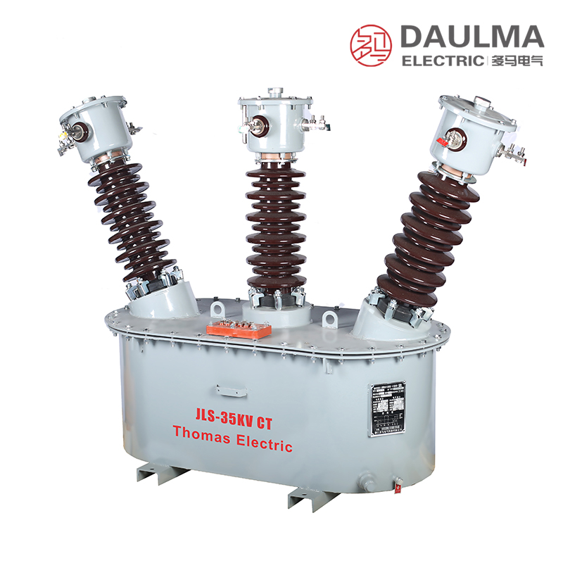
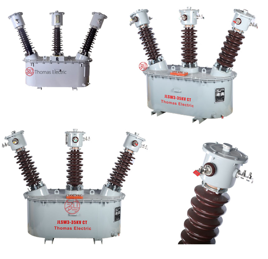
The JLSW3-35kV is an outdoor oil-immersed combined instrument transformer designed for three-phase AC power systems up to 35 kV. It integrates three single-phase fully-insulated voltage transformers (VT) in Y/Y connection with three electromagnetic current transformers (CT), one per phase, all housed within a single oil-filled tank. This compact assembly delivers simultaneous voltage and current measurement for accurate energy metering in outdoor substations and distribution networks.
Engineered as an optimized upgrade over conventional designs, the JLSW3-35kV features an integrated moisture-proof device in the tank cover to block humidity ingress, enhancing insulation integrity and extending service life. The unit offers higher capacity, reduced weight and footprint, and simplified field installation compared to legacy configurations.
Key Ratings Snapshot
| Parameter | Value |
|---|---|
| System voltage class | 35 kV |
| Rated frequency | 50 Hz / 60 Hz |
| Configuration | 3 x VT (Y/Y) + 3 x CT (A,B,C) |
| VT connection | Y/Y grounded neutral |
| CT type | Electromagnetic, toroidal core |
| Accuracy classes | 0.2 / 0.2S |
| Insulation type | Oil-immersed |
| Installation environment | Outdoor |
| Secondary voltage (VT) | 100 V or 100/√3 V |
| Secondary current (CT) | 1 A or 5 A |
Model Designation
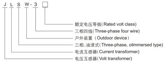
- J: Combined instrument transformer (metering box)
- L: Current transformer element
- S: Voltage transformer element (three-phase)
- W: Outdoor installation
- 3: Three-phase configuration
- 35: Voltage class (kV)
Construction
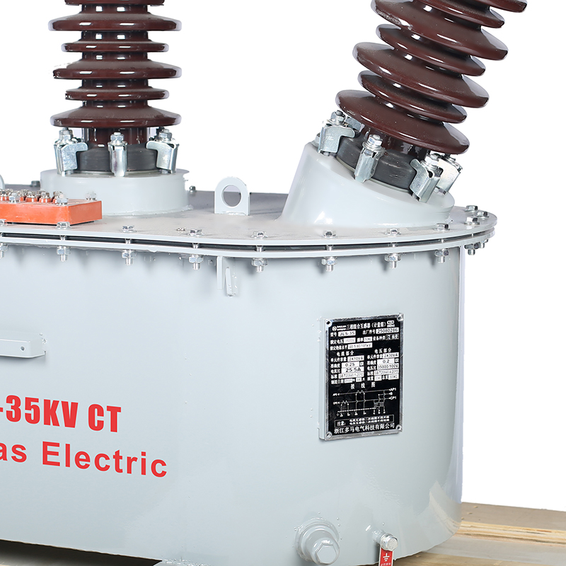
The JLSW3-35kV features a rectangular welded steel oil-filled tank housing three single-phase electromagnetic VTs and three ring-type electromagnetic CTs mounted on fixed terminal plates. The tank includes a moisture-proof cover, oil level gauge, grounding bolt, oil drain valve, and two lifting lugs for safe hoisting during installation. All internal components are fully immersed in insulating oil for superior dielectric performance and thermal stability.
The integrated moisture-proof device actively prevents external humidity from entering the oil system, significantly improving long-term reliability in humid climates compared to standard outdoor transformers. This design ensures consistent insulation strength and minimizes maintenance requirements over the product’s operational life.
Technical Parameters
Service Conditions
- Installation environment: Outdoor installation
- Altitude: Not exceeding 1000 m above sea level
- Ambient temperature: -25 deg C to +40 deg C
- Relative humidity: Daily average <= 95%, monthly average <= 90% (at +20 deg C)
- Pollution level: Per IEC 60815 / GB/T 26218
- Environmental conditions: Free from corrosive gases, explosive media, severe vibration, or salt spray
- Seismic requirements: Per applicable regional standards where specified
Technical Data
| Rated Primary Voltage (V) |
Rated Secondary Voltage (V) |
Accuracy Class |
Rated Burden (VA) |
Burden Power Factor |
|---|---|---|---|---|
| 35000/√3 | 100/√3 | 0.2 | 50 | cos phi = 0.8 (lagging) |
| 35000/√3 | 100/√3 | 0.2S | 50 | cos phi = 1.0 |
| 35000 | 100 | 0.2 | 50 | cos phi = 0.8 (lagging) |
| 35000 | 100 | 0.2S | 50 | cos phi = 1.0 |
| Rated Primary Current (A) |
Rated Secondary Current (A) |
Accuracy Class |
Rated Burden (VA) |
Burden Power Factor |
|---|---|---|---|---|
| 50 | 5 | 0.2 | 10 | cos phi = 0.8 (lagging) |
| 100 | 5 | 0.2 | 10 | cos phi = 0.8 (lagging) |
| 200 | 5 | 0.2 | 15 | cos phi = 0.8 (lagging) |
| 400 | 5 | 0.2 | 20 | cos phi = 0.8 (lagging) |
| 600 | 5 | 0.2 | 20 | cos phi = 0.8 (lagging) |
Frequently Asked Questions
Q1: Can this outdoor transformer be installed in coastal environments?
No, it must be installed in environments free from salt spray and corrosive gases. Please contact our engineering team for specialized coastal variants.
Q2: Which accuracy class is available for this 35kV voltage transformer?
The JLSW3-35KV offers 0.2 and 0.2S accuracy classes with a rated burden of 50 VA. Specify your required power factor (0.8 lagging or 1.0) during ordering.
Q3: What is the maximum altitude for installing this oil-immersed transformer?
The standard installation altitude must not exceed 1000 meters above sea level. For higher altitudes, derating factors apply; contact us for project-specific technical confirmation.
Q4: Can the primary and secondary voltage ratios be customized?
Standard configurations include 35000/√3 to 100/√3 and 35000 to 100 ratios. Custom voltage ratios are subject to factory confirmation; please provide your exact system requirements.
Q5: What factory tests are performed before shipping this combined transformer?
Standard routine tests are conducted per applicable IEC and GB standards prior to shipment. For specific type tests or third-party certifications, please confirm details with our sales team.
Q6: Are these combined transformers suitable for 35kV outdoor metering?
Yes, the JLSW3-35KV is designed for outdoor power distribution and metering in 35kV AC systems. Ensure the ambient temperature remains between -25°C and +40°C for optimal performance.
Q7: How does this transformer handle seismic activity and severe vibrations?
The unit must be installed in areas free from severe vibration. Seismic performance meets applicable regional standards where specified; provide local seismic data for verification.
Installation & Wiring
Installation Diagram
The JLSW3-35kV combined transformer must be securely mounted on a stable foundation using designated mounting points. Primary VT connections are made via high-voltage bushings, while CT primary connections use through-type busbar or bolted terminals. Maintain adequate clearance for insulation, heat dissipation, oil inspection, and maintenance access. A zinc oxide arrester must be installed within 1 meter of the unit per GB 20840.4-2015.
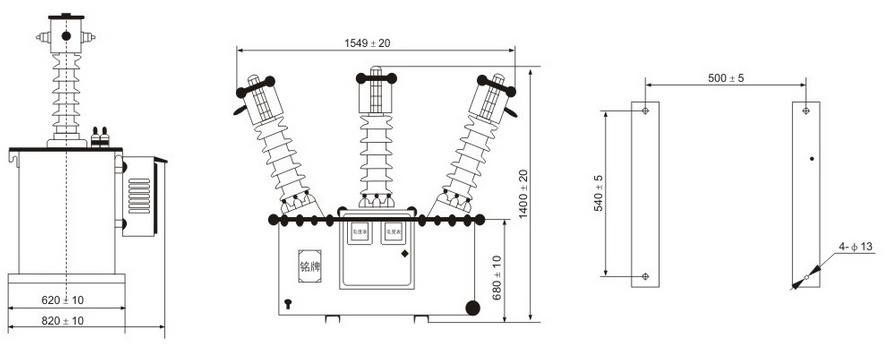
Outline Dimensions
| Dimension | Value (mm) |
|---|---|
| Overall height | 1850 |
| Overall width | 1200 |
| Overall depth | 800 |
| Bushing center spacing (phase-to-phase) | 400 |
| Mounting hole pattern | 800 x 600 |
| Minimum ground clearance | 300 |
Selection & FAQs
Selection Guide
- Select VT ratio based on system voltage: 35000/100 V for line-to-line or 35000/√3/100/√3 V for line-to-neutral measurement.
- Choose CT ratio (e.g., 100/5, 200/5) to cover expected load range while maintaining accuracy at minimum operating current.
- For revenue metering, specify 0.2 or 0.2S accuracy class per GB 17215 and utility requirements.
- Calculate total rated burden as sum of connected instrument VA ratings plus wiring losses based on cable length and cross-section.
- Confirm environmental suitability: altitude >1000 m, coastal, or heavy-pollution sites require enhanced specifications.
- Specify optional features early: integrated energy meters, communication interfaces, or special terminal arrangements.
Frequently Asked Questions
Q1: How do I correctly select the VT and CT ratios, accuracy classes, and burden ratings for the JLSW3-35kV combined transformer in a 35 kV outdoor substation used for revenue metering?
For revenue-grade metering per GB/T 17215 and IEC 61869 standards, specify VT secondary voltage as either 100 V (line-to-line) or 100/√3 V (line-to-neutral), depending on whether your metering system uses phase-phase or phase-ground references. Select CT primary current to cover 120–150% of maximum expected load—e.g., 400/5 A for a 300 A peak load—to maintain accuracy at low currents. Use 0.2S class for CTs if measuring light loads (<5% of rated current); otherwise, 0.2 suffices. VT burden must not exceed 50 VA at cos φ = 0.8 (lag) for 0.2 class or cos φ = 1.0 for 0.2S. Always sum the VA of all connected meters, test switches, and wiring (using R = ρL/A) to ensure total burden stays within rated limits.
Q2: Why does the JLSW3-35kV require a zinc oxide arrester within 1 meter, and what are the consequences of non-compliance?
Per GB 20840.4-2015 and IEC 61869-4, oil-immersed instrument transformers on 35 kV systems are vulnerable to switching surges and lightning-induced overvoltages that can cause internal insulation failure. Installing a zinc oxide (ZnO) arrester within 1 meter minimizes lead inductance, ensuring rapid clamping of transient voltages before they reach the transformer’s bushings. Omitting or distancing the arrester increases risk of dielectric breakdown, oil decomposition, and catastrophic failure—especially in areas with high lightning density or frequent capacitor bank switching. Field data shows arrester omission correlates with >60% of premature JLSW3-35kV failures in unshielded rural networks.
Q3: What are the critical installation precautions to avoid common field errors when mounting the JLSW3-35kV outdoors?
Key precautions include: (1) Never leave CT secondary windings open-circuited during or after installation—this induces dangerous overvoltages (>3 kV) and saturates the core; always short-circuit secondaries until meters are connected. (2) Ensure minimum ground clearance of 300 mm and phase-to-phase bushing spacing of 400 mm to meet IEC 60071 insulation coordination requirements. (3) Verify foundation dimensions match the 800 × 600 mm mounting hole pattern to prevent mechanical stress on bushings. (4) Install only after confirming ambient conditions comply with service limits: ≤1000 m altitude, -25°C to +40°C, and no salt spray or corrosive atmospheres. (5) Perform oil level inspection post-installation—low oil compromises both cooling and dielectric strength.
Q4: How does the integrated moisture-proof device in the JLSW3-35kV improve long-term reliability compared to conventional outdoor oil-immersed transformers?
The moisture-proof device—a desiccant-sealed breather integrated into the tank cover—actively blocks humidity ingress during thermal cycling, preventing water accumulation in insulating oil. In standard designs without this feature, repeated expansion/contraction draws moist air into the tank, increasing oil moisture content beyond 20 ppm (per IEC 60422), which accelerates cellulose insulation aging and reduces breakdown voltage. Field studies in humid regions (e.g., Southeast Asia, Gulf Coast) show JLSW3-35kV units maintain <15 ppm moisture over 10 years, versus >35 ppm in legacy units, extending expected service life from ~15 to >25 years and reducing maintenance frequency by 40%.
Q5: When should I choose 0.2S vs. 0.2 accuracy class for the JLSW3-35kV, and how does burden power factor affect performance?
Select 0.2S class when metering applications involve highly variable or low-load conditions (e.g., industrial plants with intermittent operation or renewable generation sites), as 0.2S guarantees ≤0.2% error down to 1% of rated current, whereas 0.2 class only maintains accuracy above 5%. For VTs, burden power factor is critical: 0.2 class assumes cos φ = 0.8 lagging (inductive loads like motors), while 0.2S assumes cos φ = 1.0 (resistive loads like electronic meters). Mismatched power factors—e.g., connecting a purely resistive digital meter to a VT rated for 0.8 lag—can shift phase angle error beyond ±10′, violating GB/T 20840.3 limits and causing billing inaccuracies exceeding 0.5%.
Q6: Can the JLSW3-35kV be customized for non-standard secondary currents (e.g., 1 A CT output) or higher burdens, and what are the trade-offs?
Yes, the JLSW3-35kV supports 1 A secondary CT outputs and VT burdens beyond 50 VA upon factory customization. However, 1 A CTs require larger conductor cross-sections in secondary wiring to limit burden rise (since Z ∝ I²), potentially offsetting copper savings. Higher VT burdens (e.g., 75 VA) may necessitate core redesign, increasing weight by 8–12% and delivery time by 3–4 weeks. Also, 1 A systems demand Class 0.2S CTs to maintain low-current accuracy, as 0.2 class is not defined for 1 A in IEC 61869-2 below 5% load. Always submit full system schematics to the manufacturer for burden validation and thermal verification.
Q7: How do I troubleshoot abnormal oil level or overheating in an installed JLSW3-35kV unit?
First, verify oil level against the gauge at ambient temperature—low oil indicates leakage (inspect gaskets, drain valve, and weld seams) or insufficient initial fill. Overheating (tank surface >70°C under normal load) typically stems from: (1) excessive secondary burden exceeding rated VA, causing core saturation; (2) open CT secondary inducing eddy current losses; or (3) poor ventilation due to obstructed airflow around the 1200 × 800 mm tank. Use a thermal imager to check for hot spots near bushings or terminals. If oil appears discolored or emits acrid odor, perform dissolved gas analysis (DGA): elevated CH₄/H₂ suggests partial discharge; C₂H₂ indicates arcing. Do not re-energize until root cause is resolved.
Q8: What procurement considerations should influence my decision between the JLSW3-35kV and alternative solutions like separate VT+CT banks or SF6-insulated units?
Choose the JLSW3-35kV when space, installation speed, and lifecycle cost are priorities—it reduces footprint by ~40% and cuts installation labor by 50% versus three discrete VTs and CTs. However, for coastal or high-pollution sites (IEC pollution degree IV), SF6-insulated alternatives offer better contamination resistance but at 25–35% higher upfront cost and stricter handling regulations (F-gas compliance). The JLSW3-35kV excels in standard inland 35 kV distribution substations with moderate humidity, offering 20+ year service life at lower TCO. Confirm lead time (~8–10 weeks standard) and verify manufacturer’s test reports include routine tests per GB 20840.1/4 (e.g., 70 kV 1-min power frequency withstand, partial discharge <10 pC).