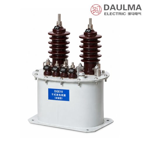
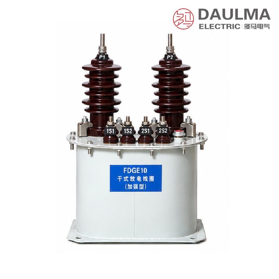
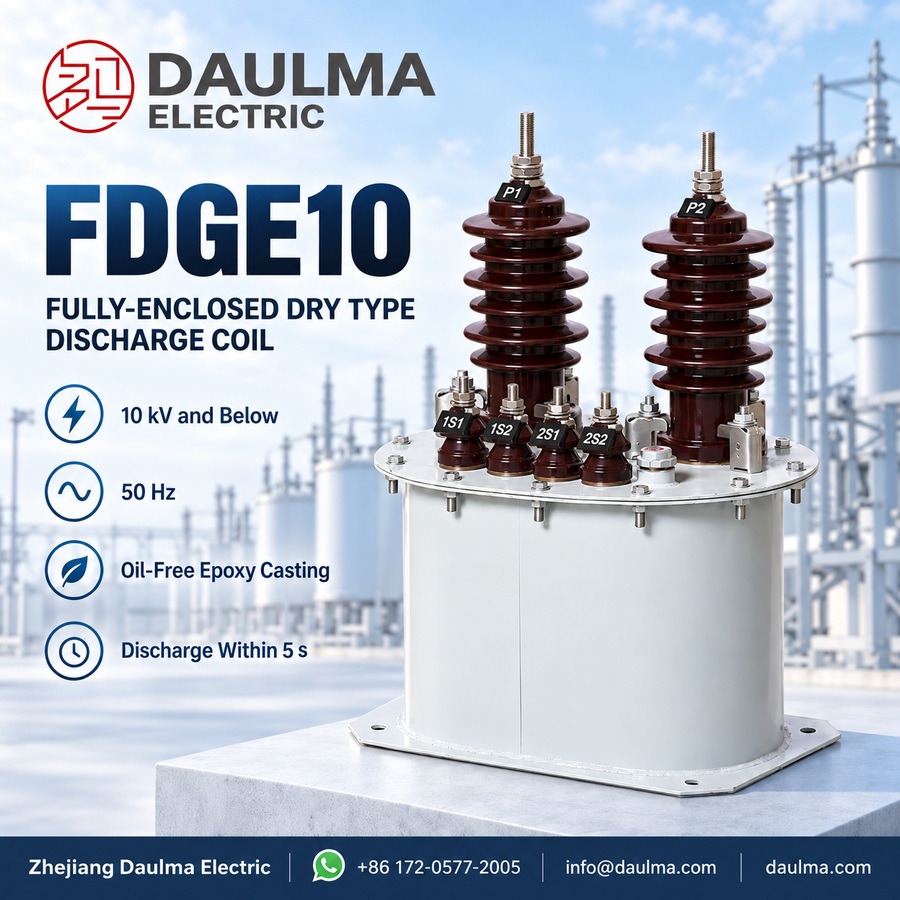
The FDGE10 fully-enclosed dry type discharge coil is a single-phase device for 50 Hz AC systems of 10 kV and below. Connected in parallel with a high-voltage shunt capacitor bank, it gives the stored charge a defined path so that the residual voltage on the bank falls to a safe level within five seconds after the bank is switched off, preventing re-closing overvoltage and allowing personnel to approach. The secondary winding serves as a voltage indicator in normal operation, and a residual-voltage winding can be supplied for relay protection on request.
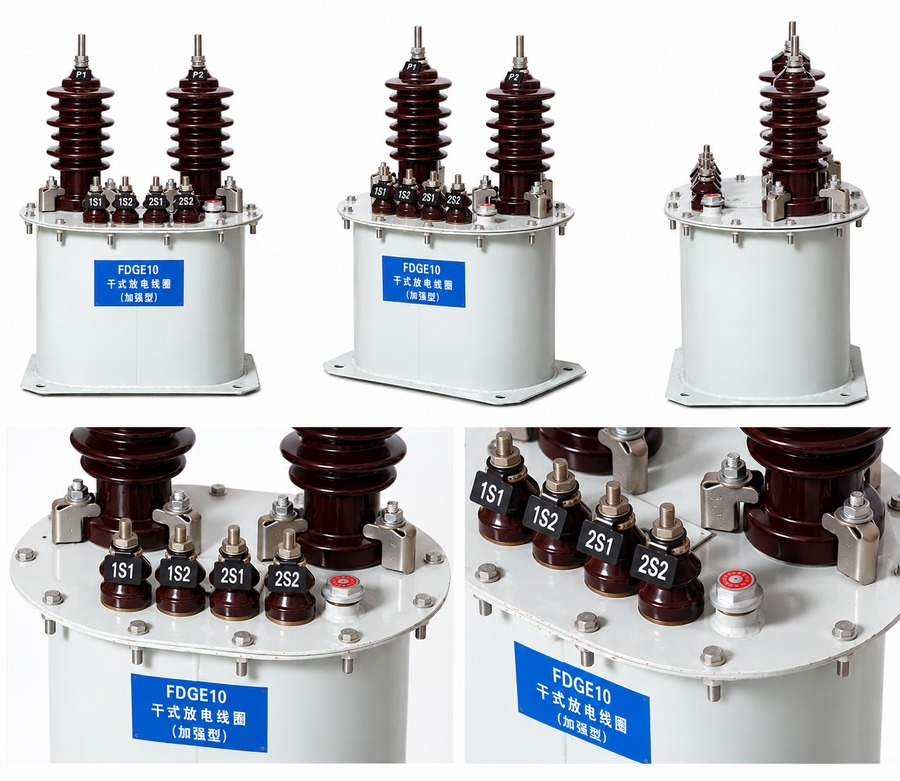
The core and windings are vacuum cast in epoxy resin and sealed inside an iron barrel, so the coil is fully enclosed, damp-proof and completely oil-free. It resists high and low temperature, electric arc, ultraviolet radiation and ageing, and is intended for continuous outdoor service as a maintenance-free replacement for outdoor oil-immersed discharge coils.
Key Ratings Snapshot
| Item | Value |
|---|---|
| Phase / installation | Single phase / outdoor |
| Rated primary voltage | 6.6/√3 kV to 12/√3 kV |
| Rated secondary voltage | 100 V (0.1 kV) |
| Accuracy class / rated output | 0.2 – 20 VA, 0.5 – 50 VA, 1 – 100 VA |
| Discharge capacity | 1.7 / 2.5 / 3.4 Mvar |
| Discharge time | Within 5 s to a safe residual voltage |
| Rated insulation level | 7.2 / 32 / 60 kV and 12 / 42 / 75 kV |
| Surface creepage distance | More than 380 mm |
| Ambient temperature | -5℃ ~ +40℃ |
| Altitude | Not more than 1000 m |
| Insulation medium | Epoxy resin vacuum casting, oil free |
| Standard | DL/T 653-1998 |
Operating Function
The coil is connected between the busbar and the neutral point of the bank, in parallel with it. While the bank is energized it works as a voltage transformer, the secondary winding supplying a proportional low voltage for voltmeters and monitoring devices. When the bank is disconnected, the stored electrostatic energy is released through the primary winding and the residual voltage falls to a safe level within five seconds, so the bank can be re-closed safely.
Construction and Design
The body is formed by epoxy resin vacuum casting and sealed inside an iron barrel, so the coil is fully enclosed and free from moisture. The cast structure resists high and low temperature, electric arc, ultraviolet radiation and ageing, and suits continuous outdoor service. The unit is compact and light with low no-load loss and strong overvoltage withstand; it needs no maintenance and replaces outdoor oil-immersed discharge coils.
Model Designation
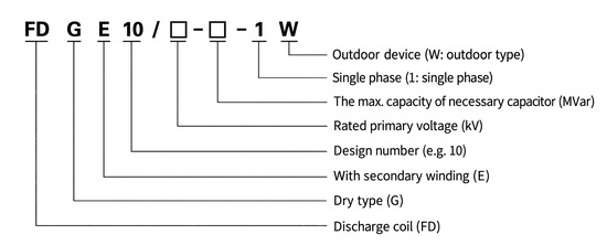
- FD — Discharge coil
- G — Dry type
- E — With secondary winding
- 10 — Design number
- / □ — Rated primary voltage, kV
- □ — Maximum matched capacitor capacity, Mvar
- – 1 — Single phase
- W — Outdoor device
Example: FDGE10/11/√3-3.4-1W denotes a design No.10 fully-enclosed dry type discharge coil with secondary winding, rated primary voltage 11/√3 kV, maximum matched capacitor capacity 3.4 Mvar, single phase, outdoor type.
Technical Parameters
Service Conditions
- Installation position: Outdoor type
- Ambient temperature: -5℃ ~ +40℃
- Altitude: Not more than 1000m
- Atmosphere: No corrosive gas or vapour; no conducting or explosive dust
- Vibration: No severe mechanical vibration at the installation site
Technical Data
| Type | Rated voltage ratio (V) | Accuracy class & rated secondary output (VA) | Discharge capacity (Mvar) | Rated insulation level (kV) | ||
|---|---|---|---|---|---|---|
| 0.2 | 0.5 | 1 | ||||
| FDGE10/6.6/√3-1.7-1W | 6.6/√3 / 0.1 | 20 | 50 | 100 | 1.7 | 7.2/32/60 |
| FDGE10/7.2/√3-1.7-1W | 7.2/√3 / 0.1 | 1.7 | 7.2/32/60 | |||
| FDGE10/11/√3-1.7-1W | 11/√3 / 0.1 | 1.7 | 12/42/75 | |||
| FDGE10/11/√3-2.5-1W | 11/√3 / 0.1 | 2.5 | 12/42/75 | |||
| FDGE10/11/√3-3.4-1W | 11/√3 / 0.1 | 3.4 | 12/42/75 | |||
| FDGE10/12/√3-1.7-1W | 12/√3 / 0.1 | 1.7 | 12/42/75 | |||
| FDGE10/12/√3-2.5-1W | 12/√3 / 0.1 | 2.5 | 12/42/75 | |||
| FDGE10/12/√3-3.4-1W | 12/√3 / 0.1 | 3.4 | 12/42/75 | |||
Standards
- The products accord with DL/T 653-1998 “Specification of discharge coils for high voltage parallel connection capacitor for order”
- Rated frequency: 50Hz
- Load power factor: COSφ = 0.8 (lagging)
- Surface creepage distance: more than 380 mm
Installation & Wiring
Installation Diagram
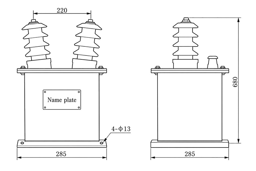
The coil stands on a flat foundation with the base plate level, anchored through the four fixing holes. The primary winding is connected in parallel with the bank between the busbar and the neutral point; the secondary circuits are brought out to the terminal compartment and wired separately from the protection relay. The enclosure must be connected to the substation earthing grid. Being oil-free and fully enclosed, the unit is built for continuous outdoor service; keep the terminal compartment reachable and confirm the cable entry against the approved drawing.
Key Outline Dimensions
| Item | Dimension |
|---|---|
| Overall height, base to top of primary bushing | 680 mm |
| Enclosure base plate, front view | 285 mm |
| Enclosure base plate, side view | 285 mm |
| Primary bushing centre distance | 220 mm |
| Foundation fixing holes | 4 pieces, 13 mm diameter |
| Top cover arrangement | Two inclined primary bushings plus one smaller secondary terminal cover |
| Nameplate position | Front face of the enclosure |
All dimensions are in millimetres. Anchor the base plate through the four fixing holes on a flat foundation and confirm the final outline against the approved drawing supplied with the order.
Applications
- Oil-free, maintenance-free discharge coils for outdoor shunt capacitor banks
- Reactive power compensation and power-factor correction at altitudes up to 1000 m
- Cast surfaces with more than 380 mm creepage distance for substation atmospheres
- Direct replacement of outdoor oil-immersed discharge coils
Selection & FAQs
Selection Guide
- State the capacitor bank rated voltage. Taps run from 6.6/√3 to 12/√3 kV; types up to 7.2/√3 kV carry insulation level 7.2 / 32 / 60 kV, types at 11/√3 and 12/√3 kV carry 12 / 42 / 75 kV.
- Match the bank capacity. Discharge capacity is 1.7, 2.5 or 3.4 Mvar and appears directly in the type designation.
- Specify accuracy class and burden. 0.2 (20 VA), 0.5 (50 VA) or 1 (100 VA) according to the connected metering or indication load at COSφ = 0.8 (lagging).
- Confirm the site. Outdoor installation, -5℃ to +40℃, altitude not above 1000 m, with more than 380 mm surface creepage.
- Compare neighbouring designs. For an indoor bank of the same voltage range see the FDGE9 fully-enclosed dry type coil; for other outdoor cast or oil-immersed designs see the FDGE11 and FDGEC ranges.
FAQs
Q1: How do I read the type designation, for example FDGE10/11/√3-2.5-1W?
FD is discharge coil, G dry type, E with secondary winding, 10 the design number. The figure after the slash is the rated primary voltage in kV, so 11/√3 means 11/√3 kV; 2.5 is the maximum matched capacitor capacity in Mvar; 1 is single phase and W the outdoor type.
Q2: What is the difference between the FDGE10 and the FDGE9 fully-enclosed coil?
Both are single-phase epoxy vacuum-cast, fully-enclosed oil-free coils covering 6.6/√3 to 12/√3 kV with accuracy classes 0.2 / 0.5 / 1. The FDGE10 is the design No.10 barreled outdoor version with 1.7 to 3.4 Mvar discharge capacities; the FDGE9 is the indoor type.
Q3: Can this coil really be installed outdoors?
Yes. The FDGE10 is a barreled outdoor product: the epoxy-cast body sealed in the iron barrel is damp-proof and resists ultraviolet radiation and ageing, with no oil joints or breather that weather could affect. The limits are -5℃ to +40℃ ambient and 1000 m altitude; it is a direct replacement for outdoor oil-immersed discharge coils.
Q4: What do the rated insulation levels 7.2 / 32 / 60 and 12 / 42 / 75 mean?
They give the voltage class, power-frequency and lightning-impulse withstand in kV. Types 6.6/√3 and 7.2/√3 kV withstand 32 kV power frequency and 60 kV impulse; types 11/√3 and 12/√3 kV withstand 42 kV and 75 kV. Never substitute a lower insulation level for a higher system voltage.
Q5: What do the accuracy class and rated secondary output mean?
During normal operation the secondary winding acts as a voltage indicator for meters and relays. Class 0.2 suits metering duty at 20 VA burden; classes 0.5 and 1 give 50 VA and 100 VA for coarser indication, all at a load power factor of 0.8 lagging.
Q6: What data do I need to provide when ordering?
Please state the bank rated voltage and capacity in Mvar, the required accuracy class and secondary output in VA, system frequency, site altitude and ambient temperature, the system insulation level, and the preferred terminal arrangement. Special demands beyond the tabulated data are settled by technical agreement.