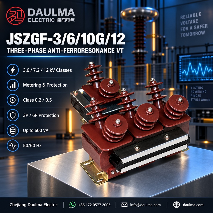
Overview
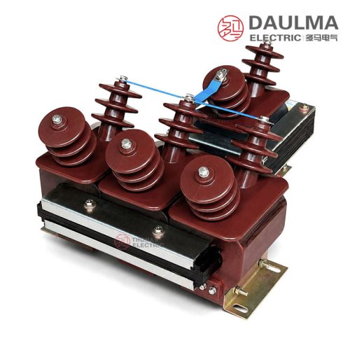
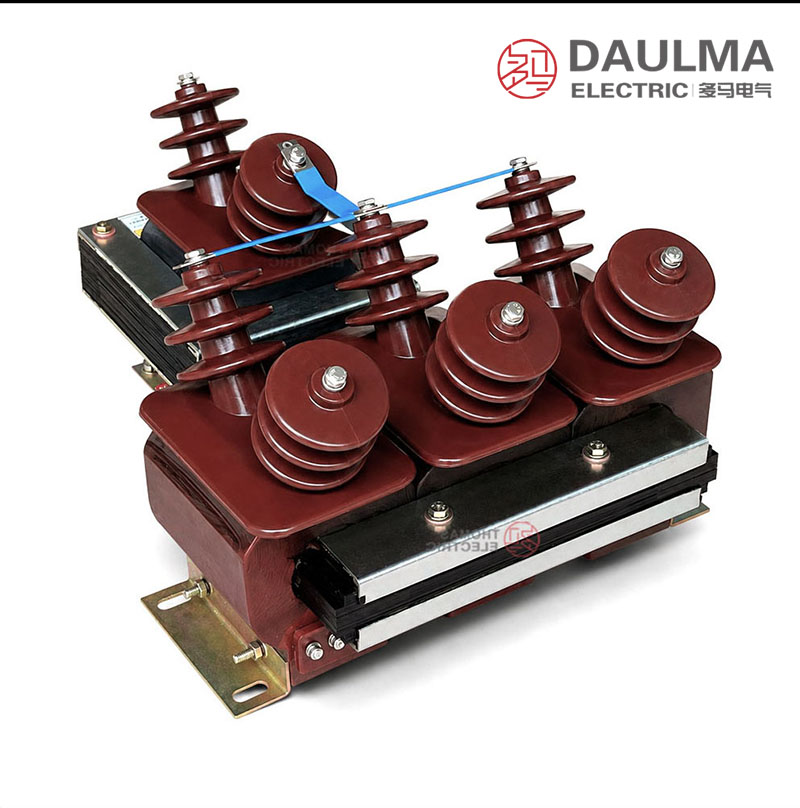
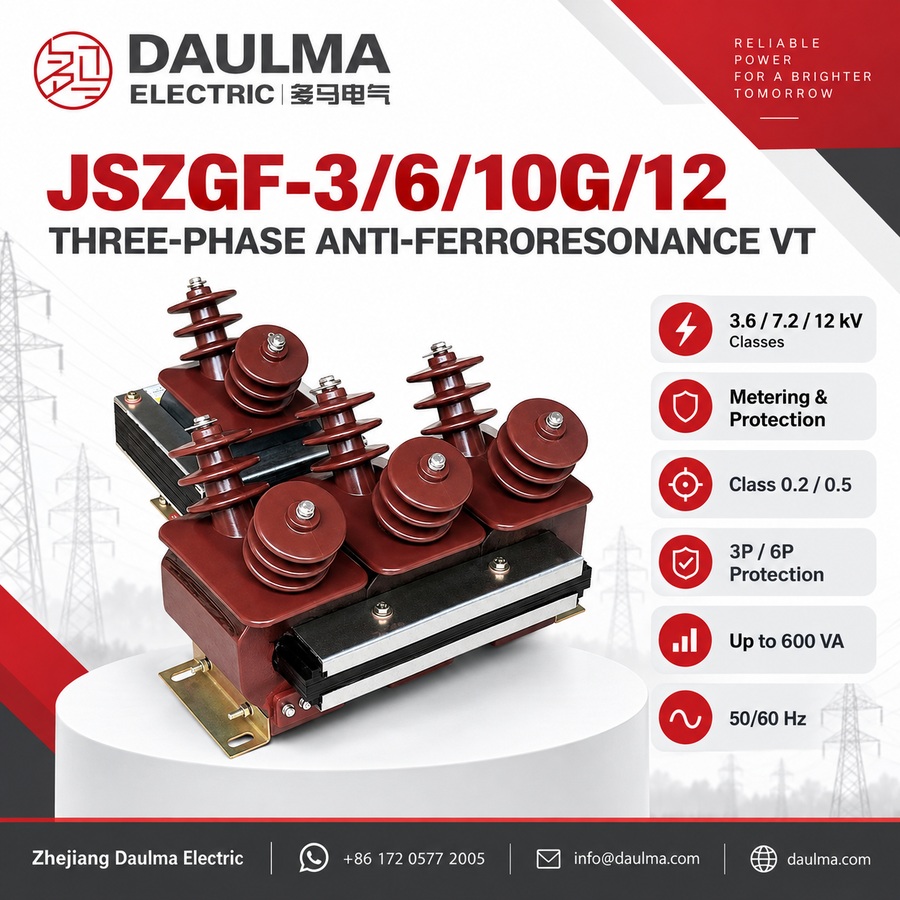
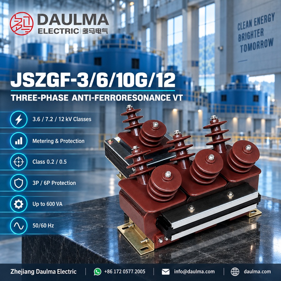
The JSZGF-3, JSZGF-6, and JSZGF-12 are three-phase anti-ferroresonance voltage transformers designed for 3.6kV, 7.2kV, and 12kV indoor medium-voltage switchgear applications. These units feature an epoxy cast-resin insulation system with a semi-enclosed structure and fully insulated primary windings, ensuring reliable operation under single-phase grounding conditions without abnormal temperature rise.
They deliver standardized secondary voltage outputs for metering, residual-voltage monitoring, grounding fault detection, and relay protection circuits. The transformers comply with relevant IEC and national standards for accuracy, insulation levels, and thermal performance, making them suitable for continuous duty in distribution networks where ferroresonance suppression is critical to prevent VT damage..
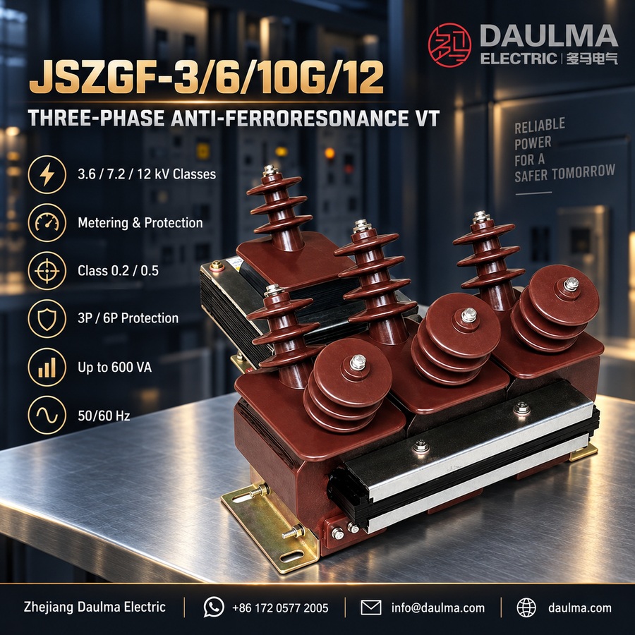
Key Ratings Snapshot
| Parameter | Rating |
|---|---|
| Voltage Class | 3.6kV / 7.2kV / 12kV |
| Primary Voltage | 3.6kV, 7.2kV, or 12kV (line-to-line) |
| Secondary Voltage | 100/√3 V (phase), 100 V (residual) |
| Accuracy Class | 0.5 / 3P (typical) |
| Thermal Burden | Per IEC 61869-3 |
| Insulation Level (JSZGF-12) | 12/42/75kV (Ur/Ud/Uimp) |
| Insulation Level (JSZGF-6) | 7.2/32/60kV |
| Insulation Level (JSZGF-3) | 3.6/25/40kV |
| Construction Type | Epoxy cast-resin, semi-enclosed |
| Phase Configuration | Three-phase |
| Ferroresonance Protection | Built-in design feature |
| Application Environment | Indoor switchgear only |
Construction
The JSZGF series features a robust epoxy cast-resin construction with a semi-enclosed design. The primary windings are fully insulated and embedded within the cast-resin body, providing excellent dielectric strength and mechanical stability. This construction ensures long-term reliability in indoor switchgear environments and supports continuous operation during single-phase-to-ground faults without excessive heating. The anti-ferroresonance characteristic is achieved through optimized magnetic circuit design and core material selection, reducing the risk of overvoltage-induced transformer failure under capacitive loading or intermittent grounding conditions.
Technical Parameters
Service Conditions
- Installation: indoor switchgear or protected electrical installation
- Ambient temperature: -30°C to +40°C according to special service requirement; standard sample range -25°C to +40°C
- Altitude: not over 1000m
- Installation environment: free from fire hazard and dangerous explosive conditions
- Installation environment: free from strong vibration and severe mechanical impact
- Neutral point grounding: directly grounded according to the anti-ferroresonance design requirement
Technical Parameters
The JSZGF series is a three-phase anti-ferroresonance voltage transformer with indoor semi-enclosed epoxy cast-resin insulation, rated for voltage classes of 3.6kV, 7.2kV, and 12kV. It operates within an ambient temperature range of -25°C to +40°C at altitudes up to 1000m, complies with GB20840.3-2013 and IEC61869-3:2011 standards, and supports various accuracy and output configurations for metering and protection applications.
| Type | Voltage Ratio(V) |
Accuracy class / Rated output (VA) |
Limit output(VA) |
Rated insulated level(kV) |
|---|---|---|---|---|
| JSZGF-3 | 3000/√3 : 100/√3 : 100 | 0.2/6P(3P)—20/100 | 600 | 3.6/25/40 |
| JSZGF-6 | 6000/√3 : 100/√3 : 100 | 0.5/6P(3P)—40/100 | 7.2/30/60 | |
| JSZGF-12 | 10000/√3 : 100/√3 : 100 | 1/6P(3P)—80/100 | 12/42/75 | |
| JSZGF-6 | 6000/√3 : 100/√3 : 100/√3 : 100/√3 | 0.2/0.2/6P(3P)—15/15/100 | 500 | 7.2/30/60 |
| JSZGF-12 | 10000/√3 : 100/√3 : 100/√3 : 100/√3 | 0.2/0.5/6P(3P)—15/20/100 | 12/42/75 | |
| JSZGF-6 | 6000/√3 : 100/√3 : 220/√3 : 100/3 | 0.2/3/6P(3P)—15/400/100 | 500 | 7.2/30/60 |
| JSZGF-12 | 10000/√3 : 100/√3 : 220/√3 : 100/3 | 0.5/3/6P(3P)—20/400/100 | 12/42/75 |
Installation & Wiring
Installation Diagram
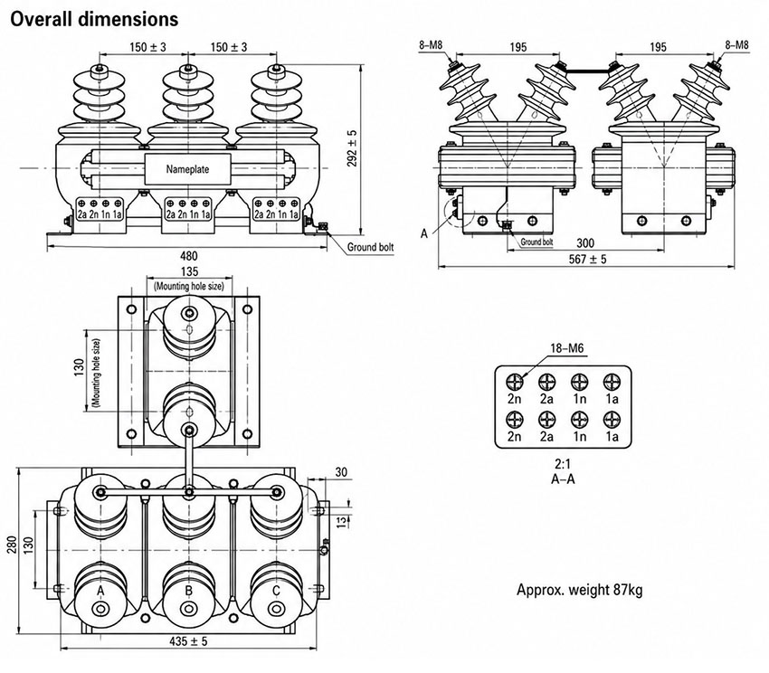
The JSZGF-12 series must be installed in accordance with the approved outline drawing, switchgear layout, and this installation diagram. The unit features a three-phase integrated cast-resin structure with multiple primary bushings, secondary terminal groups, and a base-mounted design. Mounting is achieved using 8-M8 bolts through the provided mounting holes, with a mounting reference width of 130 mm.
Wiring Diagram
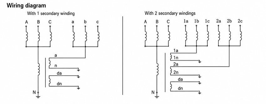
Primary and secondary terminals must be connected strictly according to the approved wiring diagram. Wiring configurations may vary depending on whether the unit has one or two secondary winding groups. Residual-voltage and protection secondary circuits should be wired in alignment with the project-specific protection scheme. Terminal markings must be verified prior to commissioning. Neutral-point grounding and anti-ferroresonance connections must follow the project wiring diagram to ensure proper operation and safety.
Selection & FAQs
Selection Guide
- Match the verified ratio: select the 3/√3kV, 6/√3kV or 10/√3kV primary with its corresponding insulation class.
- Choose the winding configuration: select standard measurement/protection, dual measurement, or the 220/√3V auxiliary version according to the approved schematic.
- Correct the dual-winding data: the table lists three accuracy duties but omits one secondary voltage in the ratio; obtain a complete winding schedule.
- Validate overvoltage duty: confirm rated voltage factor, duration and neutral grounding before relying on the stated 120% or earth-fault endurance.
- Approve protection and installation: confirm whether external primary fuses are required, plus terminal diagram, burden, mounting, grounding and site conditions.
Frequently Asked Questions
Q1: Can this anti-ferroresonance voltage transformer be installed outdoors?
No, it is strictly designed for indoor switchgear or protected electrical installations. The environment must remain free from fire hazards, explosive conditions, and severe mechanical vibration. Outdoor applications require different product series.
Q2: Which accuracy class is available for metering applications?
The 0.2 accuracy class is available for precise metering, paired with 6P or 3P for protection. Rated outputs range from 20 to 100 VA depending on the configuration. Specify your exact secondary burden requirements during ordering.
Q3: What neutral grounding configuration is required for installation?
The neutral point must be directly grounded to fulfill the anti-ferroresonance design requirements. This applies to all 3.6kV, 7.2kV, and 12kV models in the JSZGF series. Verify your system grounding scheme with our engineering team.
Q4: Does this voltage transformer comply with international IEC standards?
Yes, it fully complies with GB20840.3-2013 and IEC61869-3:2011 standards. The semi-enclosed epoxy cast-resin insulation ensures reliable performance up to 12kV. Request the specific type test certificates for your project documentation.
Q5: How are custom voltage ratios handled for specific projects?
Standard ratios include 3000/√3 : 100/√3 : 100 for 3kV systems. Custom voltage ratios for 6kV, 10kV, or 12kV applications are subject to factory confirmation. Please provide your single-line diagram for technical evaluation.
Q6: Where is the JSZGF series voltage transformer primarily applied?
It is a three-phase anti-ferroresonance voltage transformer used for metering and protection in medium-voltage switchgear. It operates effectively at altitudes up to 1000m and ambient temperatures between -25°C and +40°C. Contact sales for application-specific guidance.
Q7: Why is direct neutral grounding required for this transformer?
Direct grounding is required to suppress ferroresonance overvoltages in non-effectively grounded systems. This design ensures stable operation for the 3.6kV, 7.2kV, and 12kV rated insulation levels. Consult our technical department if your system uses alternative grounding methods.