Overview
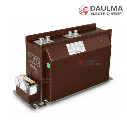
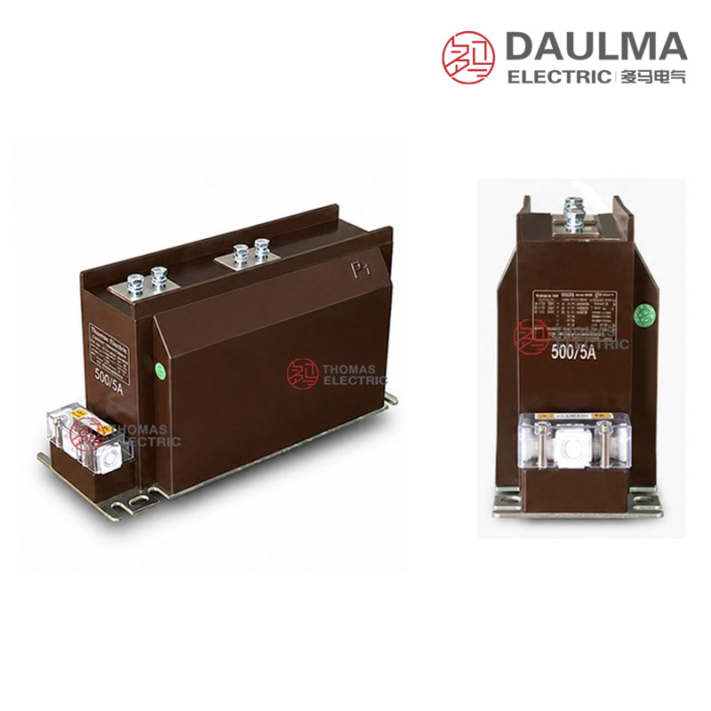
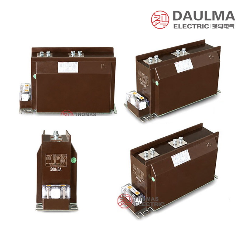
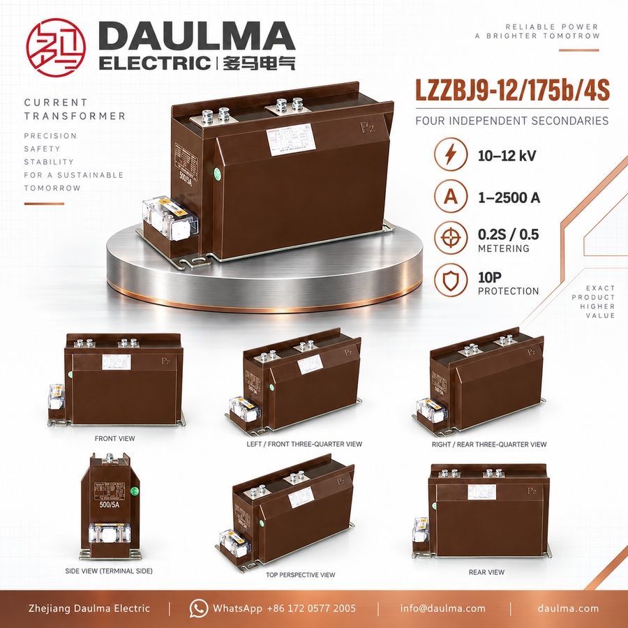
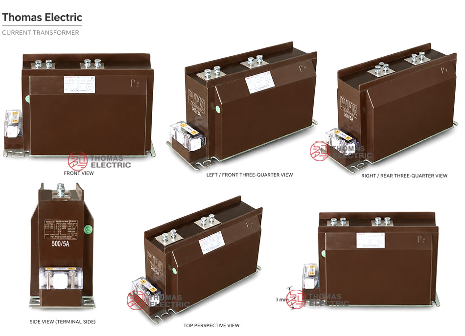
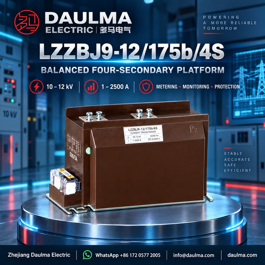
The LZZBJ9-12/175b/4S (also designated AS12/175b/4S) is an indoor, epoxy cast-resin insulated current transformer designed for 10kV, 11kV, and 12kV class medium-voltage AC power systems. It features a fully enclosed, support-type structure suitable for installation in metal-clad switchgear.
This multi-secondary CT supports combined metering, measurement, and protection functions with accuracy classes such as 0.2S, 0.5, and 10P. It is commonly used in feeder monitoring, energy metering, relay protection, and substation automation systems compliant with IEC standards for indoor applications.
Key Ratings Snapshot
| Parameter | Rating |
|---|---|
| Voltage Class | 10kV / 11kV / 12kV |
| Insulation Level | 12/42/75kV |
| Rated Frequency | 50Hz / 60Hz |
| Primary Current Range | Up to 2500A |
| Secondary Current | 1A or 5A |
| Secondary Configuration | 4S (four independent cores) |
| Metering Accuracy | 0.2S, 0.2, 0.5 |
| Protection Accuracy | 10P, 10P15, 10P20, 10P30 |
| Installation Type | Indoor, support-type on busbar |
| Insulation Material | Epoxy cast-resin |
| Application Standards | IEC 61869 series |
| Design Series | LZZBJ9 / AS12 platform |
Model Designation
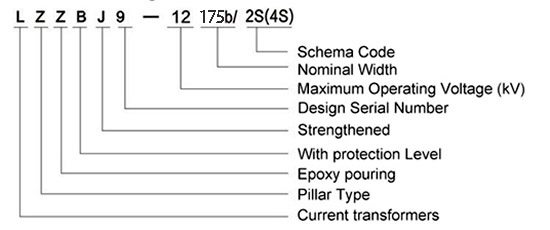
- L: Current transformer
- Z: Indoor type / support structure
- Z: Epoxy resin casting insulation
- B: Protection level available
- J: Strengthened design
- 9: Design serial number
- 12: 12kV class maximum operating voltage
- 175b: Nominal width / structure dimension code
- 4S: Multi-secondary schematic code for four secondary functions
- AS12: Alternative IEC-style 12kV series designation for the same CT platform
Construction
The LZZBJ9-12/175b/4S features a robust indoor construction with a fully enclosed epoxy cast-resin insulated body. The primary conductor is integrated into a support-type structure suitable for direct mounting onto busbars within metal-clad switchgear. The epoxy resin provides reliable electrical insulation between the high-voltage primary circuit and multiple low-voltage secondary windings, ensuring stable performance under normal indoor operating conditions. Each of the four secondary cores is magnetically and electrically isolated to serve distinct functions—such as billing metering, general measurement, main protection, and backup protection—without interference. The 175b frame dimension offers adequate mechanical strength and terminal spacing for typical medium-voltage panel layouts.
Technical Parameters
Service Conditions
- Installation location: indoor medium-voltage switchgear
- System voltage: 10kV, 11kV and 12kV class networks
- Rated frequency: 50Hz / 60Hz
- Ambient temperature: -5°C to +40°C
- Installation environment: should be free from severe vibration, conductive dust, corrosive gas, explosive medium, heavy pollution and abnormal condensation.
- Special conditions: For high altitude, humid, coastal, high-pollution or special switchgear conditions, technical confirmation is required before ordering.
Technical Parameters
The LZZBJ9-12/175b/4S is an epoxy cast-resin current transformer designed for indoor 10kV–12kV systems. It operates within an ambient temperature range of -5°C to +40°C, complies with GB 20840.2-2014 and IEC 61869-2:2012 standards.
| Rated primary current (A) |
Accuracy classed combination |
Rated Output (VA) |
Short-time thermal current (kA/1s) |
Rated dynamic current (kA) |
||
|---|---|---|---|---|---|---|
| Class 1 | Class 2 | Class 3 | ||||
| 20,30,40,50,75,100 | 0.2/0.2/5P10 | 10 | 10 | 40 | 150×I1n | 375×I1n |
| 0.2/0.5/5P15 | 10 | 15 | 30 | |||
| 0.2/0.5/5P20 | 10 | 15 | 20 | |||
| 0.2/5P10/10P15 | 10 | 20 | 20 | |||
| 0.5/5P10/10P20 | 10 | 20 | 15 | |||
| 150,200 | 0.2/0.2/5P10 | 10 | 10 | 40 | 31.5 | 80 |
| 0.2/0.5/5P15 | 10 | 15 | 30 | |||
| 0.2/0.5/5P20 | 10 | 15 | 20 | |||
| 0.2/5P10/10P15 | 10 | 20 | 20 | |||
| 0.5/5P10/10P20 | 10 | 20 | 15 | |||
| 300,400 | 0.2/0.2/5P10 | 10 | 10 | 40 | 45 | 112.5 |
| 0.2/0.5/5P15 | 10 | 15 | 30 | |||
| 0.2/0.5/5P20 | 10 | 15 | 20 | |||
| 0.2/5P10/10P15 | 10 | 20 | 20 | |||
| 0.5/5P10/10P20 | 10 | 20 | 15 | |||
| 500 | 0.2/0.2/5P10 | 10 | 10 | 40 | 63 | 130 |
| 0.2/0.5/5P15 | 10 | 15 | 30 | |||
| 0.2/0.5/5P20 | 10 | 15 | 20 | |||
| 500 | 0.2/5P10/10P15 | 10 | 20 | 20 | 63 | 130 |
| 0.5/5P10/10P20 | 10 | 20 | 15 | |||
| 600,800 | 0.2/0.2/5P10 | 10 | 10 | 40 | 63 | 130 |
| 0.2/0.5/5P15 | 10 | 20 | 40 | |||
| 0.2/0.5/5P20 | 10 | 20 | 30 | |||
| 0.2/5P10/10P15 | 10 | 20 | 30 | |||
| 0.5/5P10/10P20 | 10 | 20 | 20 | |||
| 1000,1200,1250 | 0.2/0.2/5P10 | 15 | 15 | 40 | 80 | 160 |
| 0.2/0.5/5P15 | 15 | 30 | 30 | |||
| 0.2/0.5/5P20 | 10 | 30 | 20 | |||
| 0.2/5P10/10P15 | 15 | 30 | 30 | |||
| 0.5/5P10/10P20 | 30 | 30 | 20 | |||
| 1500 | 0.2/0.2/5P10 | 15 | 15 | 40 | 100 | 160 |
| 0.2/0.5/5P15 | 15 | 30 | 40 | |||
| 0.2/0.5/5P20 | 15 | 30 | 30 | |||
| 0.2/5P10/10P15 | 15 | 30 | 30 | |||
| 0.5/5P10/10P20 | 30 | 30 | 20 | |||
| 2000 | 0.2/0.2/5P10 | 15 | 15 | 40 | 100 | 160 |
| 0.2/0.5/5P15 | 15 | 30 | 40 | |||
| 0.2/0.5/5P20 | 15 | 30 | 30 | |||
| 0.2/5P10/10P15 | 15 | 30 | 30 | |||
| 0.5/5P10/10P20 | 30 | 30 | 20 | |||
| 2500 | 0.2/0.2/5P10 | 20 | 20 | 40 | 100 | 160 |
| 0.2/0.5/5P15 | 20 | 40 | 40 | |||
| 0.2/0.5/5P20 | 20 | 40 | 30 | |||
| 0.2/5P10/10P15 | 20 | 30 | 30 | |||
| 0.5/5P10/10P20 | 40 | 30 | 20 | |||
Installation & Wiring
Installation Diagram
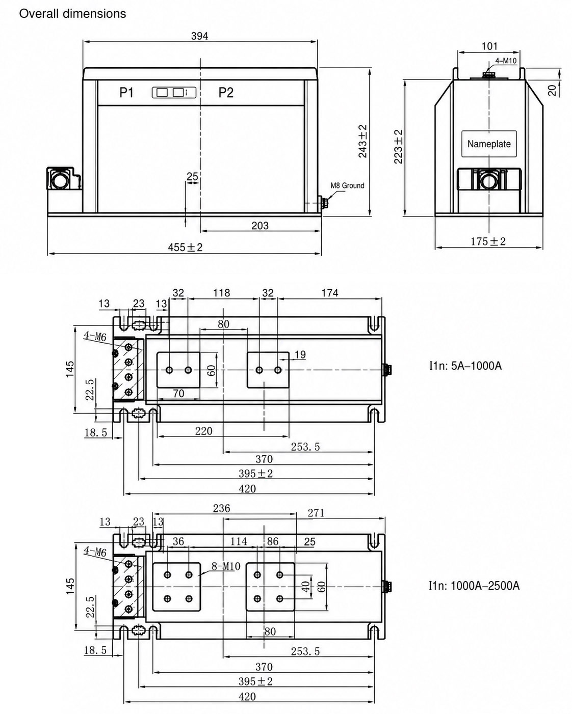
The LZZBJ9-12/175b/4S and AS12/175b/4S current transformers are installed as indoor support-type units, mounted vertically within switchgear compartments. Primary conductors pass through the central aperture and connect to the top-mounted primary terminals, while secondary wiring is accessed from the lower terminal block arranged according to the 4S multi-secondary schematic. Ensure adequate clearance for busbar routing, phase separation, and secondary cable management during installation.
Selection & FAQs
Selection Guide
- Choose the 175b platform when the 150b body is too compact but the wider 185b structure is unnecessary for the switchgear layout.
- Select a 1A–2500A primary ratio from load, metering resolution and fault study; confirm unusually low primary ratios separately.
- Define all four 1A/5A circuits individually as metering, monitoring, main protection or backup protection with their class and terminals.
- Obtain a four-core burden schedule because the source lists only three VA values in many combinations despite the 4S designation.
- Verify thermal/dynamic current, exact primary conductor/terminal arrangement, mounting drawing, 12/42/75kV insulation, clearances and grounding.
Frequently Asked Questions
Q1: Can this epoxy cast-resin current transformer be installed outdoors?
No, it is strictly designed for indoor medium-voltage switchgear. The installation environment must be free from conductive dust and corrosive gases. Contact us for outdoor alternatives.
Q2: What are the short-circuit withstand capabilities for this model?
The short-time thermal and dynamic currents depend on the selected primary current rating. Please refer to the specific technical datasheet for exact kA values. Subject to factory confirmation based on your system fault levels.
Q3: Which accuracy class combination is standard for protection and metering?
The standard configuration includes a 0.2/0.2/5P10 accuracy class combination. This provides high precision for metering and reliable 5P10 protection. Specify your exact core requirements during ordering.
Q4: Does this 12kV current transformer comply with international IEC standards?
Yes, it fully complies with IEC 61869-2:2012 and GB 20840.2-2014 standards. These certifications ensure global compatibility for your medium-voltage projects. Request the specific type test reports for your tender.
Q5: How to order this CT for high altitude environments?
Special environmental conditions require prior technical confirmation before ordering. We can customize the design for high altitude, coastal, or high-pollution areas. Submit your site details for engineering review.
Q6: When should this 10kV current transformer be selected?
It is selected for 10kV to 12kV indoor medium-voltage switchgear systems operating at 50Hz or 60Hz. Ambient temperatures must remain between -5°C and +40°C. Verify your switchgear dimensions for proper fitment.
Q7: Who manufactures this epoxy resin current transformer for 12kV systems?
We are a specialized manufacturer of medium-voltage instrument transformers. The LZZBJ9-12 series is produced using advanced epoxy cast-resin technology. Contact our sales team for factory audit details.