Overview
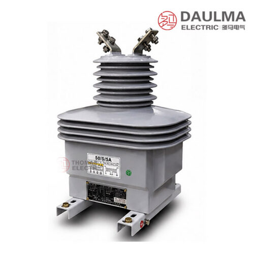
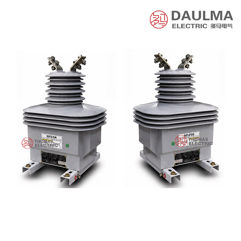
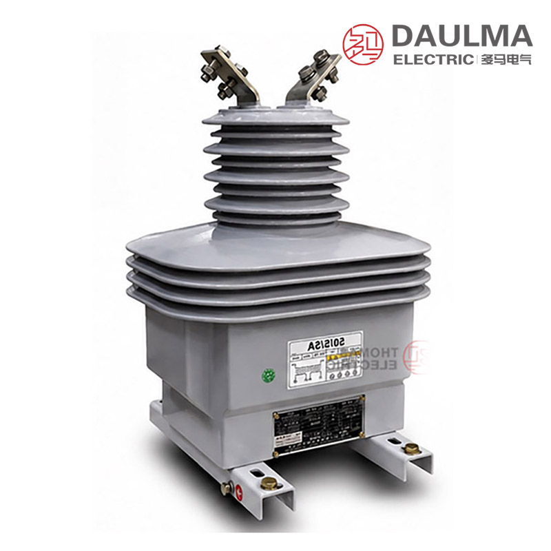
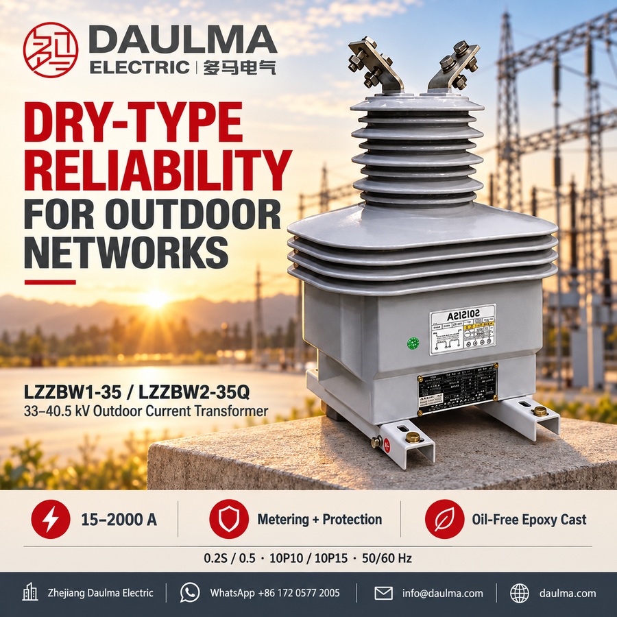
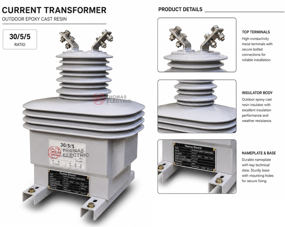
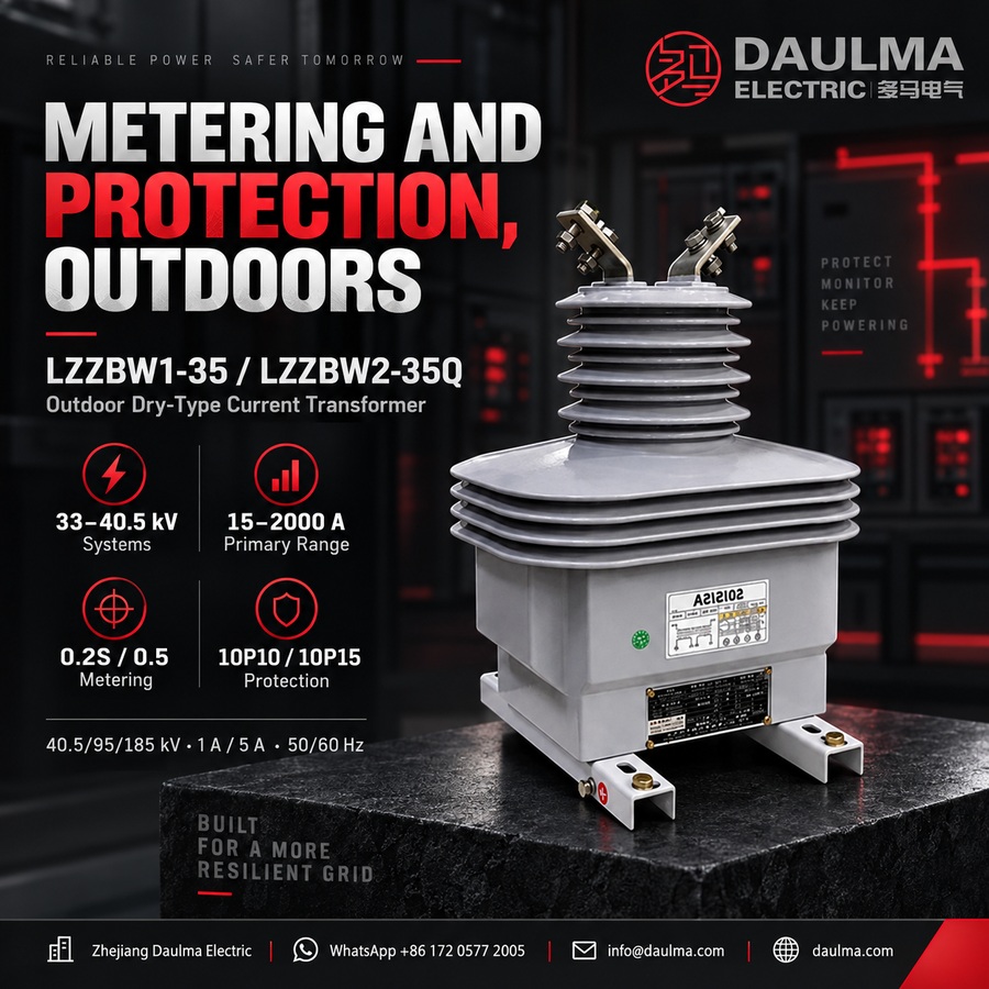
The LZZBW1-35 and LZZBW2-35Q are outdoor dry-type current transformers designed for 33kV, 35kV, and 40.5kV AC power systems. They feature a fully enclosed epoxy cast-resin insulation structure, providing high dielectric strength, mechanical robustness, and long-term reliability in exposed outdoor environments.
These units support both metering (e.g., 0.2S, 0.5) and protection (e.g., 10P10, 10P15) accuracy classes, making them suitable for feeder monitoring, utility revenue metering, and relay protection in substations, industrial plants, and renewable energy collection systems. They comply with standard requirements for 50Hz or 60Hz networks and are rated for altitudes up to 1000m with no oil or hazardous materials.
Key Ratings Snapshot
| Parameter | Rating |
|---|---|
| Voltage class | 33kV / 35kV / 40.5kV |
| Rated insulation level | 40.5/95/185kV |
| Rated frequency | 50Hz or 60Hz |
| Rated secondary current | 5A or 1A |
| Metering accuracy classes | 0.2S, 0.2, 0.5 |
| Protection accuracy classes | 10P10, 10P15 |
| Installation type | Outdoor |
| Insulation material | Epoxy cast-resin |
| Structure | Pillar-type, fully enclosed |
| Ambient temperature range | -5°C to +40°C |
| Altitude limit | ≤ 1000m |
| Application | Measurement, metering, relay protection |
Model Designation
- L: Current transformer.
- Z: Pillar-type / post-type structure.
- Z: Epoxy resin cast insulation.
- B: Metering and protection winding capability.
- W: Outdoor type.
- 1 / 2: Structural platform or design sequence.
- 35: 35kV-class platform (covers 33kV–40.5kV systems).
- Q: Enhanced or project-specific outdoor variant.
Construction
The LZZBW1-35 and LZZBW2-35Q utilize a pillar-type, fully enclosed epoxy cast-resin body that integrates primary and secondary windings into a monolithic, weather-resistant housing. The primary conductor passes vertically through the center of the unit, with top-mounted primary terminals for secure connection. The secondary windings are housed internally and brought out to a front-access terminal box, facilitating easy wiring and inspection. The epoxy resin provides excellent tracking resistance, UV stability, and moisture protection, eliminating the need for oil or gas insulation. This dry-type construction ensures maintenance-free operation and safe deployment in high-humidity or environmentally sensitive outdoor locations.
Technical Parameters
Service Conditions
- Ambient temperature: -5°C to +40°C reference; special outdoor service conditions by agreement
- Installation: Outdoor
Technical Parameters
The LZZBW1-35 and LZZBW2-35Q are outdoor epoxy resin cast current transformers designed for 33kV/35kV/40.5kV systems, with a rated insulation level of 40.5/95/185kV. They operate at 50Hz or 60Hz, support primary currents from 15A to 2000A, and comply with IEC 61869-1, IEC 61869-2, GB/T 20840.1, and GB/T 20840.2 standards.
| Model | Rated primary current (A) | Accuracy classes combination | Rated output (VA) | Rated short-time thermal current (kA/1s) | Rated dynamic current (kA) |
|---|---|---|---|---|---|
| LZZBW2-35Q | 15 | 0.2S/0.5, 0.2S/10P10, 0.5/10P10, 10P10/10P10, 10P15/10P15 | 30/50, 30/30, 30/20, 20/20, 15/15 | 3 | 7.5 |
| LZZBW2-35Q | 20 | 0.2S/0.5, 0.2S/10P10, 0.5/10P10, 10P10/10P10, 10P15/10P15 | 30/50, 30/30, 30/20, 20/20, 15/15 | 4 | 10 |
| LZZBW2-35Q | 30 | 0.2S/0.5, 0.2S/10P10, 0.5/10P10, 10P10/10P10, 10P15/10P15 | 30/50, 30/30, 30/20, 20/20, 15/15 | 6 | 15 |
| LZZBW2-35Q | 40 | 0.2S/0.5, 0.2S/10P10, 0.5/10P10, 10P10/10P10, 10P15/10P15 | 30/50, 30/30, 30/20, 20/20, 15/15 | 8 | 20 |
| LZZBW2-35Q | 50 | 0.2S/0.5, 0.2S/10P10, 0.5/10P10, 10P10/10P10, 10P15/10P15 | 30/50, 30/30, 30/20, 20/20, 15/15 | 10 | 25 |
| LZZBW2-35Q | 75 | 0.2S/0.5, 0.2S/10P10, 0.5/10P10, 10P10/10P10, 10P15/10P15 | 30/50, 30/30, 30/20, 20/20, 15/15 | 15 | 37.5 |
| LZZBW2-35Q | 100 | 0.2S/0.5, 0.2S/10P10, 0.5/10P10, 10P10/10P10, 10P15/10P15 | 30/50, 30/30, 30/20, 20/20, 15/15 | 21 | 52.5 |
| LZZBW2-35Q | 150 | 0.2S/0.5, 0.2S/10P10, 0.5/10P10, 10P10/10P10, 10P15/10P15 | 30/50, 30/30, 30/20, 20/20, 15/15 | 31.5 | 78.75 |
| LZZBW2-35Q | 200 | 0.2S/0.5, 0.2S/10P10, 0.5/10P10, 10P10/10P10, 10P15/10P15 | 30/50, 30/30, 30/20, 20/20, 15/15 | 45 | 112.5 |
| LZZBW2-35Q | 400 | 0.2S/0.5 | 50/50 | 63 | 157.5 |
| LZZBW2-35Q | 500 | 0.2(0.5)/10P10 | 50/30 | 63 | 157.5 |
| LZZBW2-35Q | 600 | 0.2(0.5)/10P15 | 50/20 | 63 | 157.5 |
| LZZBW2-35Q | 800 | 0.2(0.5)/10P20 | 50/15 | 63 | 157.5 |
| LZZBW2-35Q | 1000 | 10P10/10P10 | 30/30 | 80 | 200 |
| LZZBW2-35Q | 1000 | 10P15/10P15 | 20/25 | 80 | 200 |
Note: If user’s data go beyond the above-mentioned scopes, they may be subject to an agreement between manufacturer and purchaser.
Installation & Wiring
Installation
The LZZBW1-35 / LZZBW2-35Q is installed outdoors on a stable mounting plate, steel bracket, pole-mounted structure or substation foundation. The product drawings show different outline dimensions according to current range, including structures for 15–400A, 500–1000A and 1200–2000A. Before installation, the mounting hole layout, conductor direction, primary terminal arrangement, grounding position and secondary terminal box access should be confirmed with the approved drawing.
Windings & Terminal Marking
The primary terminals are normally marked P1 and P2. The secondary terminals are arranged in the front terminal box and should be connected according to the approved wiring diagram. For multi-core metering and protection configurations, each secondary winding should be assigned clearly before production.
| Terminal | Function | Application Note |
|---|---|---|
| P1 / P2 | Primary terminals | Used for primary current direction and polarity reference. |
| S1 / S2 | Single secondary winding | Used when one secondary output is specified. |
| 1S1 / 1S2 | First secondary winding | Usually assigned to metering or current measurement. |
| 2S1 / 2S2 | Second secondary winding | Usually assigned to relay protection. |
| 3S1 / 3S2 | Additional secondary winding when specified | Used for backup protection, independent monitoring or additional relay circuit. |
| Grounding point | Secondary / base grounding reference | One point of the secondary circuit and the CT base should be grounded according to project practice. |
Selection & FAQs
Selection Guide
- Choose the exact W1, W2 or Q model from its drawing. The page defines them as structural/project variants but does not quantify their differences.
- Select the ratio and corresponding body group. Confirm the approved structure for 15A–400A, 500A–1000A or 1200A–2000A, including primary terminals and mounting.
- Specify every secondary winding. Options include measurement/protection, dual protection and selected three-output versions above 800A; map class, VA and terminals per core.
- Qualify outdoor conditions beyond standard service. The base range is only −5°C to +40°C; confirm colder climate, creepage, pollution, IP, UV, rain, salt fog, wind and icing separately.
- Verify fault and mechanical duty. Confirm thermal duration, peak current, conductor load, support strength, terminal sealing, grounding, altitude and IEC 61869 test results.
Frequently Asked Questions
Q1: Can this 35kV outdoor current transformer be applied in 33kV systems?
Yes, it is designed for 33kV, 35kV, and 40.5kV systems. It features a rated insulation level of 40.5/95/185kV. Please confirm your specific system voltage during inquiry.
Q2: Which accuracy class combination is best for revenue metering?
Select the 0.2S/0.5 or 0.2S/10P10 combinations for billing applications. This ensures high precision measurement per IEC 61869-2 standards. Contact us to specify your exact secondary output requirements.
Q3: What is the rated short-time thermal current for 30A primary?
For a 30A primary current, the rated short-time thermal current is 6kA for 1 second. The dynamic current rating is 15kA. Verify these dynamic parameters match your site fault levels.
Q4: Can the primary current be customized beyond the standard 2000A limit?
Standard models support primary currents up to 2000A. Custom ratings beyond this range are available subject to engineering confirmation. Please provide your exact primary current requirements for a tailored quote.
Q5: Are these transformers suitable for extreme cold outdoor environments?
Standard service conditions specify an ambient temperature range of -5°C to +40°C. For extreme cold conditions outside this range, special outdoor configurations are available by agreement. Contact our sales team for details.
Q6: What material is used for the outdoor transformer housing?
The LZZBW1-35 and LZZBW2-35Q models utilize epoxy resin cast housings. This material provides excellent weather resistance for outdoor installation in 35kV switchgear. Confirm specific IP protection requirements with our engineers.
Q7: Do these current transformers comply with international IEC standards?
Yes, they fully comply with IEC 61869-1 and IEC 61869-2 standards. They also meet GB/T 20840.1 and GB/T 20840.2 requirements. They operate reliably at both 50Hz and 60Hz frequencies.