Overview
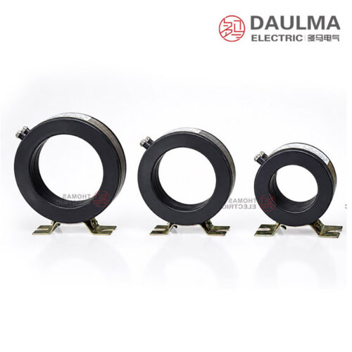
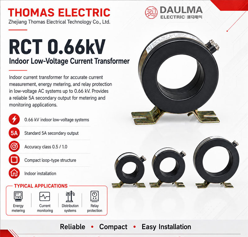
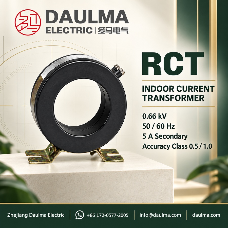
The RCT Indoor Current Transformer is a precision-engineered device designed for accurate current measurement in low-voltage electrical systems operating at 50/60 Hz with a rated voltage up to 0.66 kV. Built for reliability and consistency, it supports critical functions including energy metering, power monitoring, and relay protection in residential, commercial, and light industrial indoor installations.
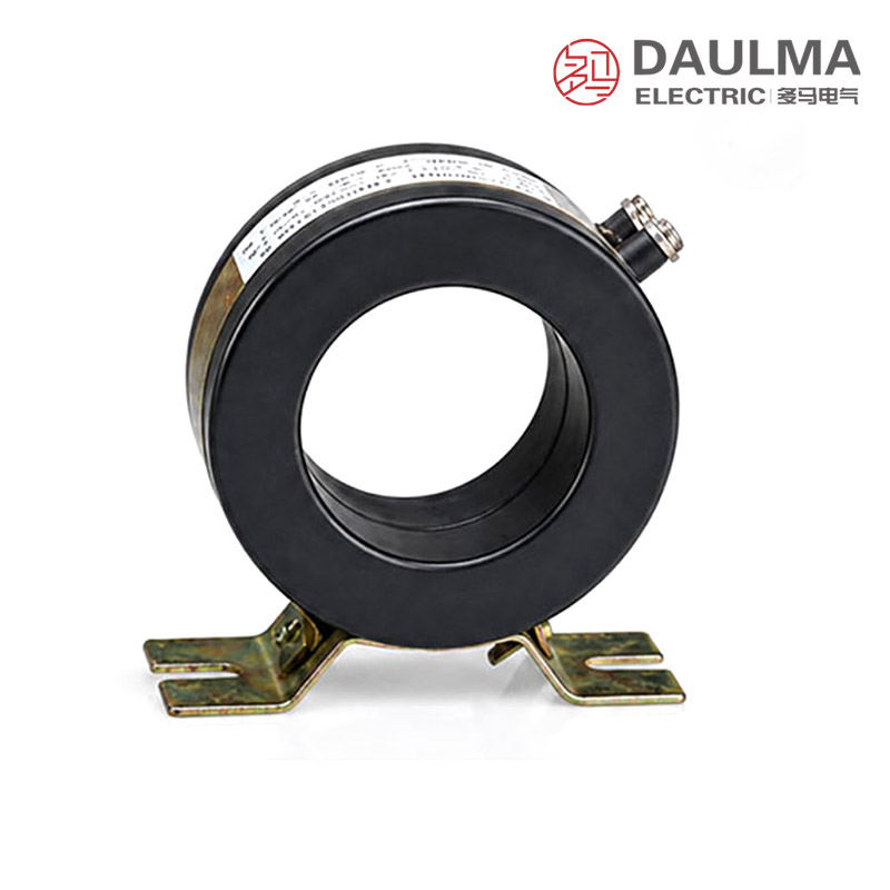
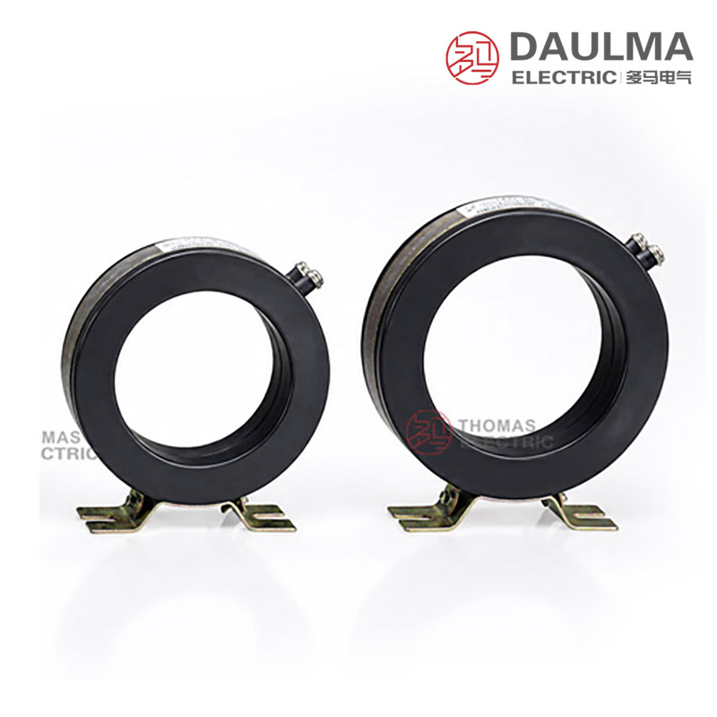
Featuring a loop-type iron core and uniformly wound secondary winding, the RCT ensures stable magnetic performance and high measurement fidelity across its operational range. Its compact, lightweight housing includes a bottom-mounted plate and a central busbar aperture, enabling secure, space-efficient mounting in switchgear panels, distribution boards, and control cabinets.
Key Ratings Snapshot
| Item | Specification (per order / nameplate) |
|---|---|
| System voltage class | 0.66 kV or below (indoor low-voltage distribution applications) |
| Rated frequency | 50 Hz or 60 Hz |
| Rated secondary current | 5 A |
| Accuracy classes | 0.5, 1.0 (metering and protection cores) |
| Rated burden | 5 VA, 10 VA, 15 VA, 25 VA (per core/winding as specified) |
| Burden power factor | cosφ = 0.8 (lagging) unless otherwise specified |
| Insulation level | 0.5 kV / 3 kV (rated insulation voltage / withstand test voltage) |
| Applicable standards | GB/T 20840.8-2007 (Instrument Transformers – Part 8: Electronic Current Transformers); JB/T 5356-2002 (General Technical Requirements for Low-Voltage Current Transformers) |
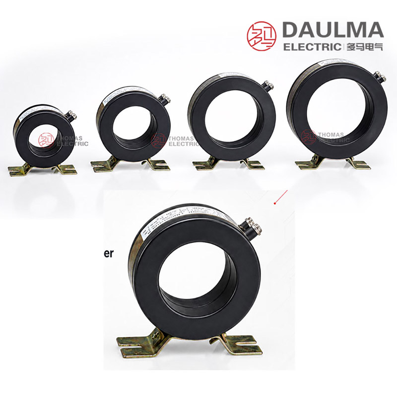
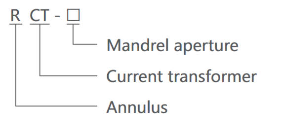
| Core aperture variants | φ35, φ58, φ90, φ110 (for different primary conductor sections) |
Model Designation
Construction
The RCT transformer employs a high-permeability loop-type iron core that minimizes hysteresis and eddy current losses, ensuring excellent linearity and phase accuracy. The secondary winding is uniformly layered and impregnated with insulating resin for enhanced dielectric strength and long-term thermal stability.
All models feature robust thermoplastic housings rated for indoor use, with screw-type secondary terminals for secure connection to meters or relays. The bottom-mounted installation plate allows direct fixation to panel surfaces, while the smooth central aperture accommodates solid or stranded busbars without requiring disconnection during installation.
Technical Parameters
Service Conditions
- Working place: Indoor
- Ambient temperature: -5 deg C to 40 deg C
- Humidity: <=80%
- Altitude: <=1000 m
- Atmospheric conditions: No serious pollution
Technical Data
| Type
(Core Aperture) |
Current Ratio (A) |
Busbar
Section (mm) |
Purchase
Specification (mm) |
Straigh
through Turn Number |
Accuracy Class
Output (VA) |
Insulation
Level (kV) |
|
|---|---|---|---|---|---|---|---|
| 0.5 | 1.0 | ||||||
| φ35 | 15/5 | — | — | 10 | 5 | 10 | 0.5/3 |
| 20/5 | — | — | 5 | 5 | 10 | ||
| 30/5 | — | — | 5 | 5 | 10 | ||
| 40/5 | — | — | 3 | 5 | 10 | ||
| 50/5 | — | — | 2 | 5 | 10 | ||
| 75/5 | — | — | 2 | 5 | 10 | ||
| 100/5 | 30 × 10 | 1 | 1 | 5 | 10 | ||
| φ58 | 150/5 | 30 × 10 | 1 | 1 | 10 | 15 | 0.5/3 |
| 200/5 | 30 × 10 | 1 | 1 | 10 | 15 | ||
| 300/5 | 50 × 10 | 1 | 1 | 10 | 15 | ||
| 400/5 | 50 × 10 | 1 | 1 | 10 | 15 | ||
| φ90 | 500/5 | 50 × 10 | 60 × 10 | 1 | 15 | 25 | 0.5/3 |
| 600/5 | 50 × 10 | 60 × 10 | 1 | 15 | 25 | ||
| 800/5 | 80 × 10 | 60 × 10 | 1-2 | 15 | 25 | ||
| 1000/5 | 80 × 10 | 60 × 10 | 1-2 | 15 | 25 | ||
| φ110 | 1200/5 | 80 × 10 | 80 × 10 | 1-2 | 15 | 25 | 0.5/3 |
| 1500/5 | 100 × 10 | 80 × 10 | 1-2 | 15 | 25 | ||
| 2000/5 | 100 × 10 | 80 × 10 | 1-2 | 15 | 25 | ||
| 2500/5 | 100 × 10 | 80 × 10 | 1-2 | 15 | 25 | ||
| 3000/5 | 100 × 10 | 80 × 10 | 1-2 | 15 | 25 | ||
| 4000/5 | 100 × 10 | 80 × 10 | 1-2 | 15 | 25 | ||
Frequently Asked Questions
Q1: Can this indoor current transformer be installed in high humidity environments?
Yes, it is suitable for humid conditions. The RCT series operates reliably with ambient humidity up to 80% and temperatures between -5°C and 40°C. Please ensure adequate ventilation in the switchgear.
Q2: Which core aperture is required for a 30x10mm busbar section?
The φ35 model supports 30×10mm busbars specifically at the 100/5A ratio. For higher current ratios like 150/5A, you must select the φ58 core aperture. Verify your exact primary current requirements.
Q3: What accuracy classes are available for measurement applications?
This transformer offers 0.5 and 1.0 accuracy classes. Both classes provide an output of 5 to 10 VA at a power factor of 0.8. Contact our engineering team for specific burden calculations.
Q4: Are factory acceptance tests provided before shipment?
Standard routine tests are performed prior to dispatch. Specific testing requirements or custom certification needs are subject to confirmation during the ordering process. Please specify your testing requirements in the inquiry.
Q5: What makes this RCT series ideal for indoor switchgear applications?
As a dedicated indoor current transformer, it ensures accurate measurement in clean environments. It is optimized for altitudes up to 1000m with no serious atmospheric pollution. Contact us for OEM integration details.
Q6: How long is the manufacturing lead time for bulk orders?
Standard production schedules apply, but exact delivery times are subject to confirmation. Lead time depends on the specific current ratio and order quantity. Contact our sales department for an accurate delivery estimate.
Installation & Wiring
Installation Diagram
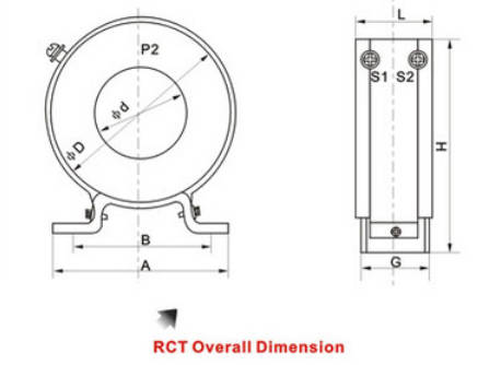
Mount the RCT transformer securely using the pre-drilled holes on the bottom plate. Pass the primary conductor straight through the central aperture, ensuring no sharp bends or mechanical stress near the transformer. Connect the secondary terminals to the metering or protection device using insulated copper wire rated for the specified burden.

Outline Dimensions
| Type | d (mm) | A (mm) | B (mm) | D (mm) | G (mm) | H (mm) | L (mm) |
|---|---|---|---|---|---|---|---|
| RCT-35 | 35 | 95 | 80 | 78 | 45 | 90 | 54 |
| RCT-58 | 58 | 110 | 88 | 100 | 45 | 113 | 56 |
| RCT-90 | 90 | 110 | 88 | 135 | 38 | 147 | 40 |
| RCT-110 | 110 | 110 | 88 | 163 | 38 | 177 | 40 |
Selection & FAQs
Selection Guide
- Select the 15/5A–4000/5A ratio from normal load, maximum current, and metering range.
- Choose a 35mm, 58mm, 90mm, or 110mm aperture by cable or busbar dimensions and clearance.
- Specify class 0.5 or 1.0 according to accuracy requirements and ratio availability.
- Calculate device and cable-loop burden and confirm the available 5VA–25VA output.
- Verify mounting plate dimensions, primary turns if required, polarity, grounding, and terminal access.
Frequently Asked Questions
Q1: How do I select the correct RCT model (e.g., RCT-35 vs. RCT-110) based on my application’s primary conductor size, current rating, and accuracy requirements?
Selection begins with verifying the physical dimensions of your primary busbar or cable against the core aperture options: RCT-35 (φ35 mm) suits conductors up to 30×10 mm for currents ≤100 A; RCT-58 (φ58 mm) handles 30–50×10 mm bars up to 400 A; RCT-90 (φ90 mm) accommodates 50–80×10 mm bars for 500–1000 A; and RCT-110 (φ110 mm) supports 80–100×10 mm bars for 1200–4000 A. Next, confirm the required accuracy class—Class 0.5 is mandatory for revenue metering per IEC/GB standards, while Class 1.0 suffices for general monitoring. Finally, ensure the rated burden (5–25 VA) matches the total impedance of connected meters, wiring, and relays at cosφ = 0.8 lagging. For example, a 600/5A RCT-90 provides 15 VA at Class 0.5, which typically supports up to 20 m of 2.5 mm² copper wire plus a Class 0.5 kWh meter.
Q2: Why does the RCT series specify different rated burdens (5 VA, 10 VA, etc.) for the same current ratio, and how does this impact system design?
Rated burden defines the maximum load (in volt-amperes) the CT secondary can drive while maintaining specified accuracy. Higher burdens (e.g., 25 VA vs. 5 VA) allow longer secondary wiring runs or connection to multiple devices without exceeding error limits. For instance, the RCT-35 50/5A model offers 5 VA at Class 0.5—sufficient only for short connections to a single meter (<5 m of 2.5 mm² Cu). In contrast, the RCT-110 2000/5A provides 15 VA at Class 0.5, enabling ~30 m of wiring or integration with both a meter and a protection relay. Always calculate total burden as Z_total = Z_meter + Z_wiring + Z_connections, where Z_wiring = (2 × L × ρ) / A (L = one-way length in meters, ρ = 0.0175 Ω·mm²/m for Cu, A = conductor area in mm²). Exceeding rated burden degrades accuracy and may violate compliance with GB/T 20840.8-2007.
Q3: What are the critical installation mistakes to avoid when mounting RCT indoor current transformers, and how do they affect performance or safety?
Three common errors compromise safety and accuracy: (1) Installing with the secondary winding open-circuited under load—this induces dangerous kV-level voltages due to core saturation, risking insulation failure and arc flash. Always short-circuit secondary terminals before disconnecting loads. (2) Bending or kinking the primary conductor near the aperture—mechanical stress distorts the magnetic field, increasing ratio and phase errors beyond Class 0.5 tolerance. Maintain ≥150 mm straight run through the core. (3) Over-torquing terminal screws (>1.2 N·m typical)—this cracks the thermoplastic housing or damages internal windings. Use calibrated torque tools per manufacturer specs. Additionally, ensure the bottom mounting plate is secured to a grounded panel surface to prevent vibration-induced loosening, which can alter magnetic coupling over time.
Q4: How does the “straight-through turn number” parameter in the RCT technical table influence low-current ratio selection (e.g., 15/5A or 20/5A)?
For ratios below ~50/5A, a single pass of the primary conductor yields insufficient ampere-turns for accurate transformation. The “straight-through turn number” indicates how many times the conductor must loop through the core to achieve the nominal ratio. For example, the RCT-35 15/5A requires 10 turns: passing a 15 A conductor 10 times creates 150 A·turns, matching the 5 A secondary (150/5 = 30:1 effective ratio, but labeled 15/5A). This technique maintains core excitation within linear range. However, multi-turn installations increase proximity effect losses and require adequate aperture clearance—verify that the conductor diameter × turn count fits within the φ35 mm window without compression. Incorrect turn count (e.g., using 5 turns instead of 10 for 15/5A) results in 100% ratio error.
Q5: Can RCT current transformers be used interchangeably with other low-voltage CT types (e.g., split-core or toroidal), and what are the trade-offs?
RCT loop-core CTs are not directly interchangeable with split-core or conventional toroidal CTs due to structural and performance differences. Split-core CTs offer retrofit convenience but suffer from air gaps that degrade accuracy (typically Class 1.0–3.0) and increase phase error—unsuitable for revenue metering. Toroidal CTs without mounting plates require custom brackets and lack standardized apertures. In contrast, RCT units provide factory-calibrated Class 0.5 accuracy, robust bottom-plate mounting for panel integration, and consistent aperture tolerances aligned with standard busbar sizes (e.g., 30×10 mm). However, RCTs require primary conductor disconnection during installation—unlike split-core—and are limited to indoor use (IP00). For new switchgear builds prioritizing metrological integrity, RCT is preferred; for retrofits on live systems, split-core may be necessary despite accuracy compromises.
Q6: What maintenance checks should be performed on installed RCT transformers to ensure long-term reliability in commercial or light industrial settings?
Routine maintenance includes: (1) Visual inspection every 12 months for cracked housings, loose mounting screws, or corroded secondary terminals—common in humid environments (>70% RH). (2) Thermal imaging under load to detect abnormal heating at terminals (>10 K above ambient indicates high contact resistance). (3) Secondary circuit continuity testing (with system de-energized) to confirm no open circuits. (4) Accuracy spot-checks every 5 years using a portable CT analyzer per JB/T 5356-2002, verifying ratio error and phase displacement at 1%, 5%, 20%, 100%, and 120% of rated current. Note that RCT’s resin-impregnated windings resist moisture ingress, but prolonged operation above 40°C ambient accelerates insulation aging—ensure panel ventilation meets service conditions.
Q7: How do procurement lead times and customization options (e.g., non-standard ratios, dual cores) affect project scheduling for RCT transformers?
Standard RCT models (e.g., 100/5A RCT-35, 600/5A RCT-90) typically ship within 2–4 weeks. Custom configurations—such as dual-core units (one Class 0.5 for metering, one Class 1.0 for protection), non-listed ratios (e.g., 125/5A), or alternate burden ratings (e.g., 7.5 VA)—require 6–10 weeks due to core recalibration and type-testing per GB/T 20840.8. Critical path projects should specify standard catalog items early; if customization is unavoidable, provide full system schematics to the supplier for burden validation. Note that aperture sizes (φ35–φ110) and insulation levels (0.5/3 kV) are fixed per mechanical design—custom apertures are not feasible. Always confirm delivery timelines include certification documentation (test reports per JB/T 5356).
Q8: How does the RCT’s compliance with GB/T 20840.8-2007 and JB/T 5356-2002 impact its suitability for international projects versus local Chinese installations?
GB/T 20840.8-2007 aligns closely with IEC 61869-8 for electronic instrument transformers, while JB/T 5356-2002 governs low-voltage CT performance in China. For projects within China, RCT’s certification ensures regulatory acceptance for utility metering and industrial safety compliance. For international deployments (e.g., Southeast Asia, Africa), verify equivalence: IEC 61869-2 covers similar accuracy, temperature, and dielectric requirements, but local utilities may demand additional certifications (e.g., KEMA, UL). Notably, RCT’s 0.5/3 kV insulation level meets IEC 61869-2’s 0.72/3 kV requirement for 0.66 kV systems via derating. However, the 5 A secondary output is less common in regions adopting 1 A standards (e.g., Europe)—confirm compatibility with existing metering infrastructure before procurement.