
Overview
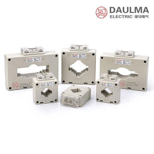
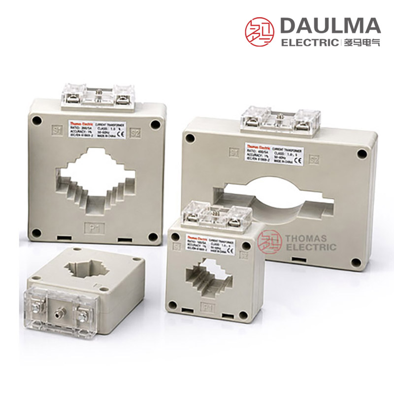
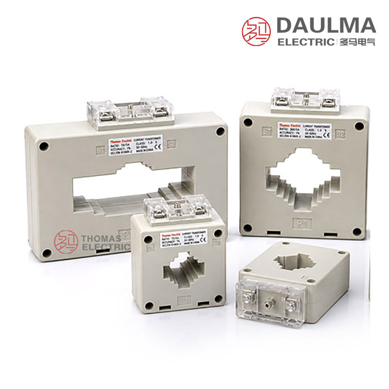
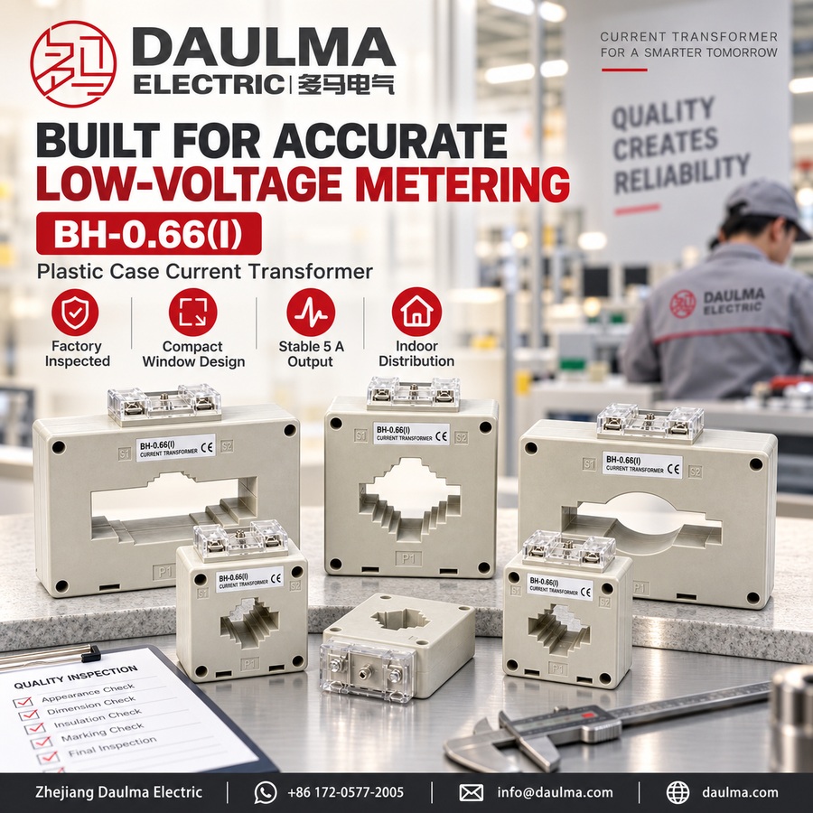
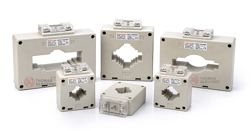
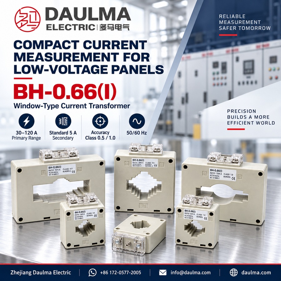
The BH-0.66(I) series low-voltage plastic case current transformers are precision electromagnetic devices engineered for accurate current measurement, energy metering, and relay protection in 0.66 kV AC power distribution systems. Utilizing a window-type (bushing) design, these transformers operate on the principle of electromagnetic induction to deliver a galvanically isolated secondary current proportional to the primary circuit—typically standardized at 5 A—without requiring direct electrical contact with the primary conductor.
Built for indoor use, the BH-0.66(I) features an epoxy resin insulated toroidal core that ensures high dielectric strength, moisture resistance, and long-term stability in industrial and commercial switchgear environments. Its compact, through-conductor structure allows easy installation around busbars or cables in space-constrained panels, making it ideal for motor control centers, distribution boards, and power quality monitoring applications.
Key Ratings Snapshot
| Parameter | Rating |
|---|---|
| System voltage class | 0.66 kV (660 V) |
| Rated frequency | 50 Hz (60 Hz optional) |
| Rated primary current | 30–120 A (selectable) |
| Rated secondary current | 5 A |
| Accuracy classes | Metering: 0.5, 1.0; Protection: 1 |
| Rated burden | As specified per winding (VA) |
| Burden power factor | cosφ = 0.8 lagging |
| Short-circuit withstand | Ith (1 s) and Idyn per order |
| Insulation level | Per GB/T 20840.2 and IEC 61869-2 |
| Applicable standards | IEC 61869-1/2; GB/T 20840.1/2; GB 1208-1997 |
| Construction type | Window-type (bushing) |
Model Designation
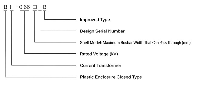
- B — Plastic Enclosure Closed Type
- H— Current transformer series
- 0.66 — Voltage class: 0.66 kV
- (I) — Desin Seril Number
- 30/40/50/60/80/100/120 — Rated primary current (A)
Construction
The BH-0.66(I) employs a window-type (bushing) construction with a central aperture for primary conductor passage. The magnetic core is ring-shaped and encapsulated in epoxy resin insulation, providing excellent dielectric performance, mechanical robustness, and resistance to moisture and thermal aging. This cast-resin insulation system ensures reliable operation in typical indoor low-voltage environments. Secondary terminals are clearly marked (K/L or S1/S2) with polarity indicators to maintain correct phase relationship for metering and protection functions. The housing is designed for secure mounting in switchgear with accessible terminal blocks for safe and straightforward wiring.
Technical Parameters
Service Conditions
- Installation environment: Indoor installation only
- Altitude: Not exceeding 2000 m above sea level (higher altitude configurations available upon request)
- Ambient temperature: −5 °C to +40 °C
- Relative humidity: Daily average ≤ 95%, monthly average ≤ 90% (at +25 °C reference)
- Environmental conditions: Free from corrosive gases, explosive atmospheres, or conductive dust; no severe vibration or mechanical shock
- Operating frequency: 50 Hz or 60 Hz
Technical Parameters
This section provides selection-oriented technical data for the BH-0.66(I) series window-type current transformer used in 0.66 kV class AC low-voltage distribution systems (50/60 Hz). Data shown below is intended for preliminary selection of accuracy class, rated burdens, and short-circuit withstand capability.
Data Reference
| Rated Primary Current (A) |
Transformation Ratio |
Accuracy Class |
Rated Output (VA) |
Typical Ith (kA, 1s) |
Typical Idyn (kA peak) |
|---|---|---|---|---|---|
| 30 | 30/5 | 0.5, 1, or Protection 1 | 2.5, 5, 10 | 0.6 | 1.5 |
| 40 | 40/5 | 0.5, 1, or Protection 1 | 2.5, 5, 10 | 0.8 | 2.0 |
| 50 | 50/5 | 0.5, 1, or Protection 1 | 2.5, 5, 10 | 1.0 | 2.5 |
| 60 | 60/5 | 0.5, 1, or Protection 1 | 2.5, 5, 10 | 1.2 | 3.0 |
| 80 | 80/5 | 0.5, 1, or Protection 1 | 2.5, 5, 10 | 1.6 | 4.0 |
| 100 | 100/5 | 0.5, 1, or Protection 1 | 2.5, 5, 10 | 2.0 | 5.0 |
| 120 | 120/5 | 0.5, 1, or Protection 1 | 2.5, 5, 10 | 2.4 | 6.0 |
Installation & Wiring
Outline Dimensions
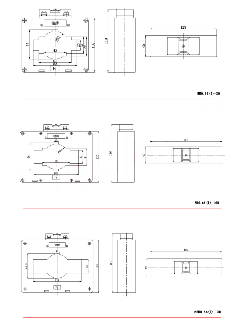

The outline dimensions illustrate the compact form factor of the BH-0.66(I) current transformer, designed for integration into space-constrained low-voltage switchgear assemblies. Key features include a central window aperture sized to accommodate standard busbar or cable cross-sections, and mounting provisions that support either bolt-down or clip-mount configurations depending on the switchgear design. Always refer to the specific dimensional drawing for the exact model being installed to ensure compatibility with primary conductors and enclosure layout.
Wiring Diagram
The wiring diagram shows the standard secondary terminal connections for metering and protection applications. Terminals are clearly marked for polarity (typically P1/P2 for primary direction and S1/S2 for secondary output). Ensure correct polarity alignment during installation to maintain accurate phase relationships in metering and relay systems. The secondary circuit must be connected to a burden (e.g., meter, relay, or shorting link) at all times when the primary is energized. One point of the secondary circuit—typically S2—should be reliably grounded in accordance with IEC 61869-2 and local electrical safety standards.
Selection & FAQs
Selection Guide
- Select a 30/5A–120/5A ratio from the branch-circuit load and normal operating range.
- Choose class 0.5 for higher metering accuracy or class 1.0 for general indication and monitoring.
- Calculate meter and cable burden, then select 2.5VA, 5VA, or 10VA rated output.
- Confirm the conductor fits the window with safe clearance and that the housing fits the panel layout.
- Verify mounting method, polarity, secondary grounding, terminal access, and indoor environmental limits.
Frequently Asked Questions
Q1: Can the BH-0.66(I) current transformer be installed outdoors?
No, it is strictly for indoor installation only. The operating environment must be free from corrosive gases and conductive dust. Contact us for outdoor-rated alternatives.
Q2: Which accuracy classes are available for the BH-0.66(I) series?
Standard accuracy classes include 0.5, 1, and Protection 1. Rated outputs range from 2.5 to 10 VA. These parameters support both precision metering and standard relay protection applications.
Q3: What is the short-circuit withstand capability for a 40A primary?
For a 40A rated primary current, the typical thermal short-circuit current (Ith) is 0.8 kA for 1 second. The dynamic peak current (Idyn) reaches 1.5 kA. Verify specific fault levels with our engineering team.
Q4: How does high altitude affect the BH-0.66(I) installation limits?
Standard models are limited to 2000 meters above sea level. Higher altitude configurations are available upon request. Derating factors may apply depending on the exact elevation and ambient temperature.
Q5: Are custom transformation ratios available for this window-type transformer?
Yes, custom ratios can be manufactured based on project needs. Standard options include 30/5 and 40/5. Submit your exact primary and secondary current requirements for a quote.
Q6: What factory tests are performed before shipment?
Routine tests are conducted according to standard manufacturing protocols. Specific type test reports and certification documents are subject to confirmation. Contact our sales team for detailed test documentation.
Q7: Where should this 0.66kV window-type current transformer be applied?
It is applied in 0.66 kV AC low-voltage indoor distribution systems for 50 Hz or 60 Hz networks. The design ensures reliable performance in environments free from severe vibration and mechanical shock.