Overview
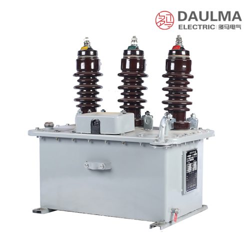
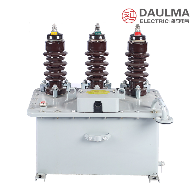
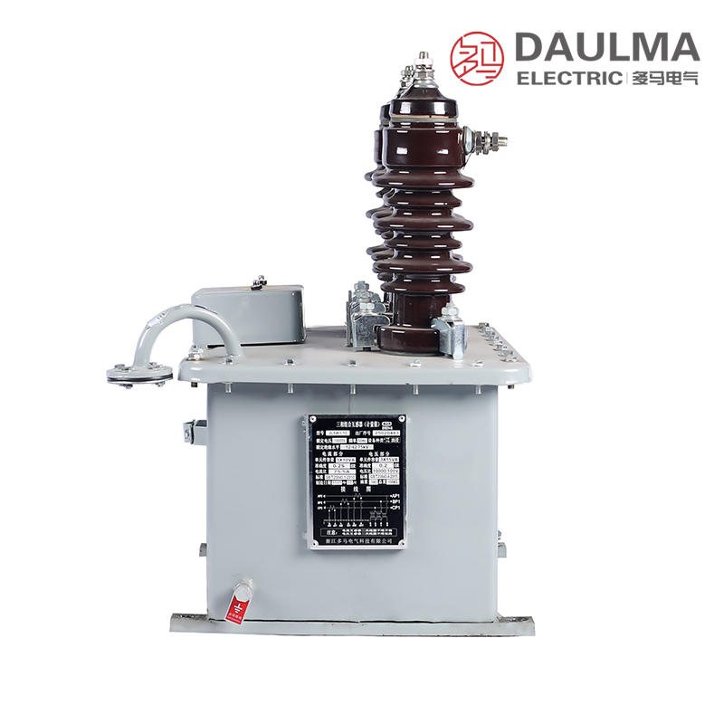
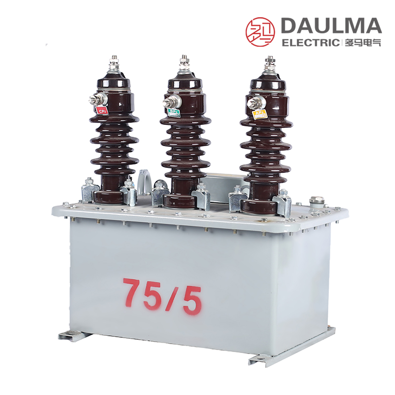
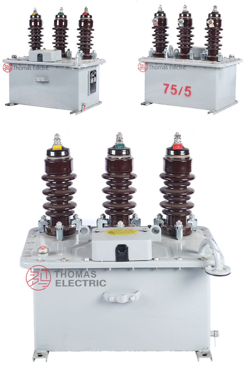
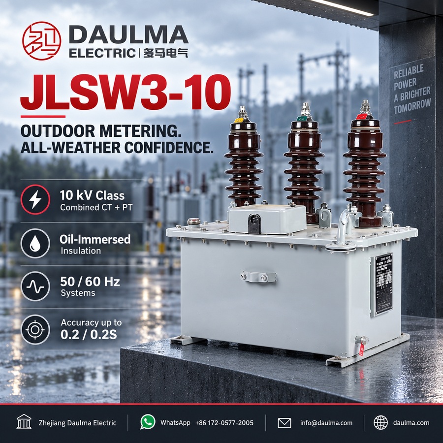
The JLSW3-10 is a 10 kV class outdoor oil-immersed three-phase combined instrument transformer, integrating both voltage and current measurement functions in a single sealed oil-filled enclosure. It features three single-phase fully-insulated voltage transformers and three electromagnetic current transformers, all housed within a robust square oil tank designed for reliable outdoor operation.
Offering accuracy classes of 0.2 and 0.2S for metering applications, the unit supports revenue-grade energy metering, relay protection, and SCADA integration in 6–10 kV distribution systems. It complies with Chinese national standards GB 20840.4-2015 (combined instrument transformers), GB 20840.2-2014 / GB 20840.1-2010 (CT), and GB 20840.3-2013 / GB 20840.1-2010 (PT).
Key Ratings Snapshot
| Parameter | Rating |
|---|---|
| System voltage class | 10 kV (6 kV variant available) |
| Rated frequency | 50 Hz / 60 Hz |
| Voltage transformer configuration | 3 × single-phase fully-insulated PT, Y/Y connection |
| Current transformer configuration | 3 × electromagnetic CT (A, B, C phases) |
| Accuracy classes | 0.2 / 0.2S (metering); protection cores as specified |
| Transformation ratio | As specified per order (customizable) |
| Rated burden | Per core/winding as specified (VA) |
| Insulation structure | Oil-immersed with moisture-prevention device |
| Installation environment | Outdoor (substations, industrial distribution) |
| Lightning protection | Zinc oxide surge arrester required within 1 meter |
Model Designation
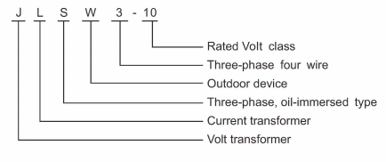
- J: Combined instrument transformer (metering unit)
- L: Current transformer component included
- S: Voltage transformer (PT) component included
- W: Outdoor installation type
- 3: Three-phase configuration (A-B-C phases)
- 10: Voltage class (kV)
Construction
The JLSW3-10 employs a compact square oil tank design optimized for outdoor durability and service accessibility. The tank houses three single-phase fully-insulated electromagnetic voltage transformers and three electromagnetic current transformers, all securely mounted on the base plate and integrated with the cover assembly. Oil immersion provides high dielectric strength and thermal stability, while an advanced moisture-prevention device on the tank cover blocks external humidity ingress. The cover includes lifting lugs, an oil level gauge, a grounding bolt, and a drain valve for maintenance. This construction ensures long-term reliability in harsh outdoor environments typical of medium-voltage distribution networks.
Technical Parameters
Service Conditions
- Installation: Outdoor (substations/industrial sites/primary metering points)
- Altitude: ≤1000 m standard; higher altitude on request
- Temperature: Per GB outdoor oil-immersed limits; extremes to be specified
- Humidity: Outdoor moisture-proof/breather protected
- Site condition: Non-corrosive, non-explosive, low vibration/impact
- Lightning: ZnO arrester required within 1 m of the unit
Technical Parameters
The JLSW3-10 is a 10 kV class outdoor oil-immersed three-phase combined instrument transformer for 50/60 Hz AC systems. It features electromagnetic CTs and single-phase PTs in Y/Y connection, with customizable transformation ratios, accuracy classes up to 0.2/0.2S, and compliance with GB 20840 series standards. Designed for altitudes up to 1000 m and standard outdoor temperature ranges per GB specifications.
Model Variants
| Parameter | JLSW3-6 | JLSW3-10 |
|---|---|---|
| System voltage class | 6 kV | 10 kV |
| Rated frequency (Hz) |
50 Hz / 60 Hz | 50 Hz / 60 Hz |
| PT configuration | 3 × single-phase, Y/Y connection | 3 × single-phase, Y/Y connection |
| CT configuration | 3 × electromagnetic type | 3 × electromagnetic type |
| Metering accuracy class | 0.2 / 0.2S | 0.2 / 0.2S |
| PT transformation ratio | Per specification (customizable) | Per specification (customizable) |
| CT transformation ratio | Per specification (customizable) | Per specification (customizable) |
| Secondary output (PT) | Per specification (VA) | Per specification (VA) |
| Secondary output (CT) | Per specification (VA) | Per specification (VA) |
| Insulation structure | Oil-immersed with moisture prevention | Oil-immersed with moisture prevention |
| Installation | Outdoor | Outdoor |
Installation & Wiring
Outline Dimensions
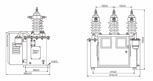
The outline dimensions and mounting details for the JLSW3-10 10kV outdoor oil-immersed combined instrument transformer are provided in the dimensional drawing above. Ensure sufficient space is allocated during installation to accommodate the unit’s physical size and to allow for proper clearances.
Selection & FAQs
Selection Guide
- Specify system voltage class (6 kV or 10 kV) according to local grid requirements.
- Define PT and CT transformation ratios for accurate three-phase metering and protection.
- Select appropriate accuracy class (0.2 or 0.2S for metering; protection cores if needed) per project specifications.
- Confirm rated burden (VA) for both PT and CT secondary windings to match connected instrumentation.
- Provide operating environment details including altitude, temperature range, humidity, and pollution level for proper insulation rating.
- Indicate any customization needs such as special ratios, high-precision versions, or integration with energy meters at the ordering stage.
Frequently Asked Questions
Q1: How far must the ZnO arrester be installed from this transformer?
Install the ZnO arrester within 1 meter of the unit. This outdoor oil-immersed combined transformer requires non-corrosive, low-vibration site conditions per GB standards. Contact our engineering team for detailed installation drawings.
Q2: What accuracy classes are available for the JLSW3-10 instrument transformers?
Accuracy classes up to 0.2 and 0.2S are available. These meet GB 20840 series standards for 10kV class systems with customizable transformation ratios. Specify your required ratio and class during your initial inquiry.
Q3: Can the JLSW3-10 be used in high-altitude environments above 1000 meters?
Standard models are designed for altitudes up to 1000 meters. This 10kV combined transformer operates within standard outdoor temperature and humidity limits per GB specifications. Please provide your exact site altitude for factory derating confirmation.
Q4: Which PT and CT configurations are offered for this 10kV combined transformer?
It features three single-phase PTs in a Y/Y connection with electromagnetic CTs. Transformation ratios are fully customizable to match your 50Hz or 60Hz AC system requirements. Request a customized technical datasheet from our procurement team.
Q5: Are routine factory tests performed before shipping the JLSW3-10 transformers?
Yes, all units undergo routine testing compliant with GB 20840 standards. The 10kV class combined transformers are verified for electrical performance prior to dispatch. Specific type test reports are subject to confirmation upon request.
Q6: Where should the JLSW3-10 outdoor oil-immersed transformer be installed?
It is designed for outdoor substations, industrial sites, and primary metering points. This 10kV class three-phase combined instrument transformer integrates measurement in a moisture-proof, breather-protected enclosure. Contact us to verify regional compliance and application suitability.